Eight-axis Cantilever Intelligent Welding Workstation
The advantages of the 8-axis robot welding workstation are as follows:
1. High precision: The 8-axis robot welding workstation has high-precision positioning and motion control capabilities, enabling precise welding operations.
2. High efficiency: The robot welding workstation can achieve automated welding, greatly improving production efficiency and work efficiency.
3. Flexibility: The 8-axis robot welding workstation has flexible motion capabilities and can adapt to different shapes and sizes of welding workpieces.
4. Reliability: The robot welding workstation adopts advanced control systems and sensors, providing stable and reliable working performance.
5. Safety: The robot welding workstation can reduce manual welding operations, reducing the safety risks for workers.
6. Cost savings: Automated welding can reduce labor costs and material waste, thereby reducing production costs.
7. Quality control: The robot welding workstation can achieve precise welding parameter control, improving welding quality and consistency.
8. Traceability: The robot welding workstation can record the welding process and parameters, achieving traceability of the welding process.
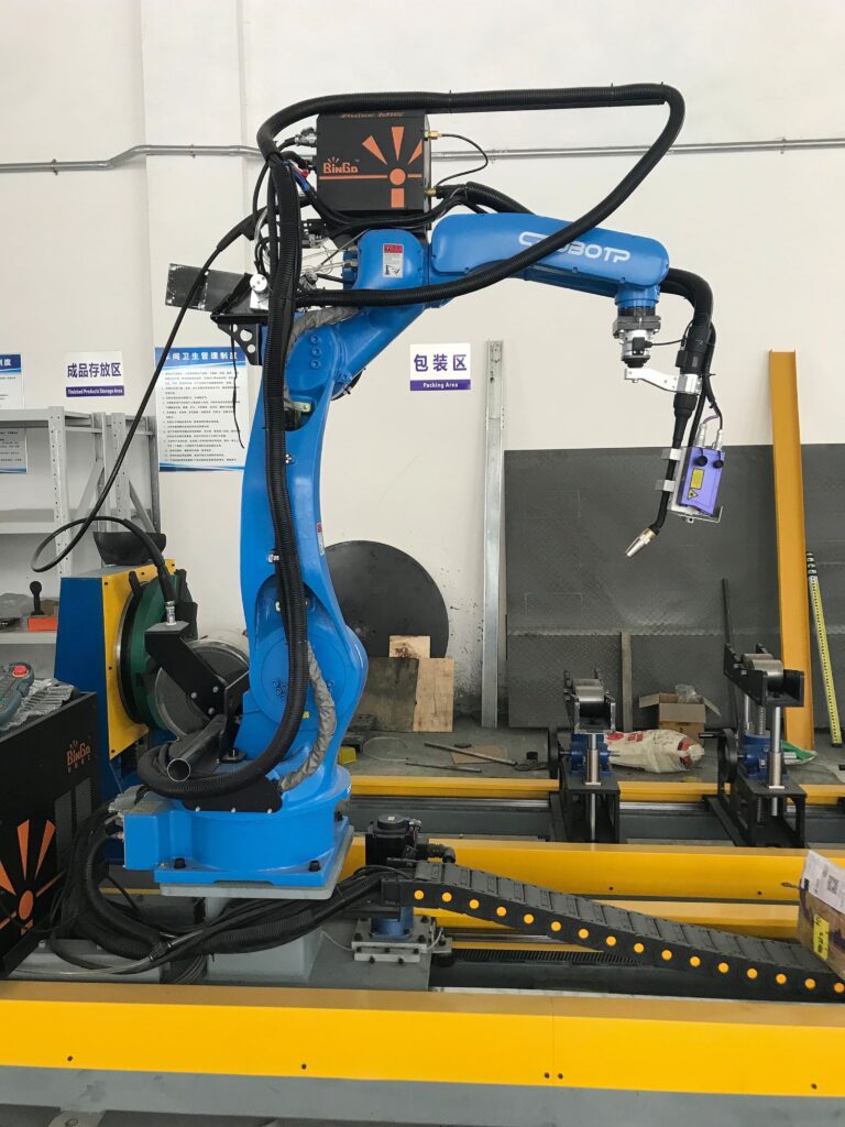
Operating System
System Interface
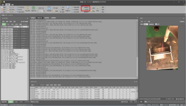
Visual Interaction Interface of Operating System
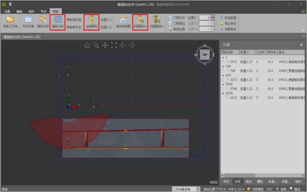
Model Driver Interface of Operating System

Function Overview
The system is a self-developed system with its main function to automatically generate the welding program according to the actual contour of the position in the model by deeply integrating
the welding process and then importing it into the 3D model to determine the position of the whole component weld through the visual system. The software is deployed on the PC system, which can be placed anywhere. Remote control can be realized through TCP/IP protocol, that is, field equipment can be directly operated for welding in the office.
The system can work normally in two shifts every day (8 hours per shift) and maintain stable accuracy;
The design drawings of the workstation have been repeatedly demonstrated and simulated, and the design strength of each component is reliable and easy to assemble and maintain. On the premise of ensuring functions, the appearance is beautiful;
All purchased parts of the workstation equipment are provided by well-known manufacturers in the industry, and the quality of all processed parts has been strictly controlled with standard strength, superior performance and stable movement;
The measurement unit of parts and instruments of workstation equipment and all drawings shall be GB standard; the design, manufacture and materials used for all instruments and parts shall conform to ISO and IEC standards or other equivalent standards;
The parts and components of the workstation are made of high-quality materials, and the selected mechanical and electrical elements are high-quality and reliable products.
Project Scheme
Product Type
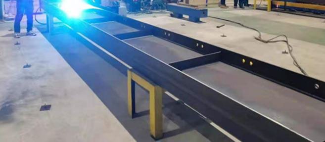
Structural dimensions
S/N | Product | Height | Width | Length |
1 | Bridge diaphragm | Vertical plate height ≤0.5m | ≤3.5m | ≤12m |
2 | H-shaped steel | Vertical plate height ≤0.5m | ≤3.5m | ≤12m |
Photos of typical products


Working environment and user preparation
Power supply: 380V±10%, 50HZ±2%, 220V±10%, 50HZ. The main distribution box at the wiring point shall be equipped with a leakage protector of more than 125A and reliably grounded. The power distribution cabinet shall be set in the middle of the station; otherwise, the length of cables provided with the vehicle will not be enough;
a) Foundation works b) Primary side wiring materials and works c) TN-S grounding system and ground wire
Operating ambient temperature: -10°C~45°C.
Operating ambient humidity: ≤90% without condensation; sufficient light and good ventilation; compressed air pressure: greater than or equal to 0.6MPa.
Compressed air: provide an air source with a pressure of 5-7Kgf/cm2, usually 4-5Kgf/cm2.
Shielding gas: CO2, Ar+CO2 gases or pipelines that meet the national standards and are supplied in a centralized manner shall be provided. The pressure of shielding gas shall be greater than 0.5MPa.
Site preparation: a) Before the equipment arrives at the site, the user shall clean up the workplace of the intelligent welding system workstation b) Provide gantry installation pads according to the levelness of the site ground c) Equipped with a manual welding machine capable of spot welding at any position d) Installation of forklift or crane coordination equipment
Overall Layout
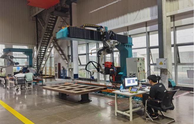
Cantilever Case Diagram
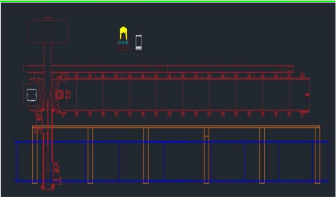
Cantilever Layout
Layout Description
The site required for the standard eight-axis cantilever standalone intelligent workstation is 3.5*13 (unit: m).
The standard eight-axis cantilever standalone intelligent workstation includes: 1 set of eight-axis cantilever, 1 set of robot, 1 set of welder, 1 set of welding gun vision and 1 set of operating system (including computer);
The optional auxiliary systems of the workstation include: gun cleaning station (optional), dust collection equipment (optional);
The user is responsible for the arrangement of the workbench frame and the welding layout between the stands
Equipment list
Equipment list of cantilever eight-axis welding workstation Number of workstations: 1 | ||||||
S/N |
Sub-item |
Name/description |
Unit |
Quantity | Brand/ manufacturer |
Remarks |
1 | Robot system | Welding robot | Set | 1 | EFT | ER10-1600 |
2 |
| Customized cable | Set | 1 | EFT |
|
3 |
| Control cabinet | Set | 1 | EFT |
|
4 | Welding equipment | Welder | Set | 1 | Ota | NBC-500RP PRO |
5 |
| Customized cable | Set | 1 | Ota |
|
6 |
| Welding gun | Set | 1 | Thelma | Water-cooled welding gun TRM605W |
7 |
| Gun cleaning station | Set | 1 | Thelma |
|
8 | Traveling system | Eight-axis cantilever | Set | 1 | EFT | GB-DJXB-2Y-13X |
9 |
| Servomotor | Set | 3 | Tama River |
|
10 |
| Customized cable | Set | 3 | EFT |
|
12 |
Vision system |
Full line-of-sight laser |
Set |
1 |
JTC | Including vision system software + bracket |
13 |
| Computer/console | Set | 1 | JTC |
|
14 |
| Intelligent system | Set | 1 | JTC |
|
Equipment configuration
Basic composition of a welding robot system:
A — welding signal cable Signal interaction between robot and welding machine;
B — Positive cable of welding machine Positive circuit of welding machine;
C — Wire feeder control cable Interactive signal between a welding machine and wire
feeder;
D — Negative cable of welding machine Negative circuit of welding machine;
E — Air pipe pipeline for conveying shielding gas;
F-Wire feeder tube Welding wire delivery pipeline
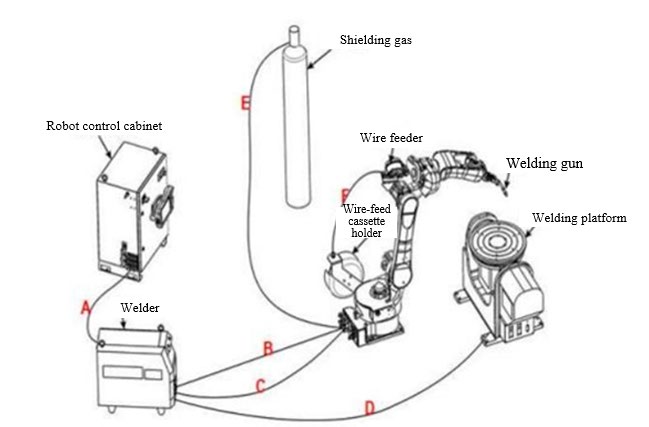
Welding Robot:
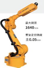
ER-10-1600
Maximum arm span: 1640mm Repeated positioning accuracy: ±0.05mm
| Allowable moment of inertia of wrist | Axis J1 | 20N.m | ||||||||||||
| Axis J2 | 20N.m | ||||||||||||||
| Axis J3 | 10N.m | ||||||||||||||
| Axis J4 | 0.625kg.m2 | ||||||||||||||
| Axis J5 | 0.625kg.m2 | ||||||||||||||
| Axis J6 | 0.2kg.m2 | ||||||||||||||
| Maximum single-axis speed | Axis J1 | 170°/sec | |||||||||||||
| Axis J2 | 160°/sec | ||||||||||||||
| Axis J3 | 180°/sec | ||||||||||||||
| Axis J4 | 330°/sec | ||||||||||||||
| Axis J5 | 360°/sec | ||||||||||||||
| Axis J6 | 600°/sec | ||||||||||||||
| Motion range of each axis | Axis J1 | ±165° | |||||||||||||
| Axis J2 | +80°/-135° | ||||||||||||||
| Axis J3 | +163°/-75° | ||||||||||||||
| Axis J4 | ±180° | ||||||||||||||
| Axis J5 | ±130° | ||||||||||||||
| Axis J6 | ±360° |
Motion range parameters
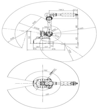
Relevant parameters of robot control system
Functional unit | Specification item | Technical indicators |
Main power supply | Rated voltage | Three-phase AC 380V±10% |
| Power supply frequency | 50Hz~60Hz, fluctuation range: ±5% |
| Power of complete machine | 3.5kW |
Control terminal | 24V power output | 24V ±5%, 10A |
| Digital output | 24-channel PNP high-level output (users can use 18 channels) |
| Digital input | 24-channel PNP high-level input (users can use 16 channels) |
| Analog input | Support for adding expansion modules |
| Analog output | Support for adding expansion modules |
| Auxiliary encoder interface | Support for adding expansion modules |
Communication interface | CAN | 1 channel, the interface is located in the controller and it supports welding machine communication |
|
Ethernet | 1 channel, the interface located in the controller, and it supports TCP/IP, MODBUS_TCP, FINS_TCP and ETHERNET/IP |
| EtherCAT | 1 channel, it supports remote IO module and ANYBUS gateway module expansion. |
|
|
|
Outline dimensions of the control cabinet | W555mm×D560mm×H1165mm (excluding aviation plug) | |
Weight | 125kg | |
Environment | Protection grade of electric cabinet | IP54, cooling unit IP30 |
| Cooling method | Air cooling |
| Installation mode | Vertical placement |
| Operation place | Indoor, free of direct sunlight, dust, no corrosive gas, combustible gas, oil mist, water vapor, dripping or salt, etc. |
| Ambient temperature | 0℃~45℃ |
| Ambient humidity for use | 80%RH without condensation (40°C) |
Communication Function
Communication function | Available or not | Supplementary notes |
MES | √ | MES function based on TCP/IP communication, which can read various states of the robot |
TCP/IP communication | √ | Support SOCKET communication as a server or client, and support free parsing of strings |
Modbus-TCP | √ | As a slave station (server) of Modbus-TCP, the robot supports data transmission, external startup and status reading |
Profibus-DP | X | This model is an RP2 controller without a DP hardware interface |
Ethernet/IP | √ | Robot as a slave station |
Profinet | X | The default configuration is RP2 controller, which needs to be upgraded to RP2-RPO controller |
CANopen | √ | Support communication of Ota and Megmeet welding machine protocols |
EtherCAT | √ | Support EtherCAT slave station equipment and ANBUS series gateway to convert EtherCAT communication into other bus protocols |
Other | √ | Fixed Visual Communication and Conveyor Tracking Visual Communication Based on TCP/IP Protocol |
Brand of main accessories
Name | Brand | Use |
Reducer | Green | J5, J6 axis |
Reducer | Aoyi | J1, J2,J3 and J4 axes |
Servomotor | Tama River | Axes J1~J6 |
Driver | Qingneng Dechuang S7 | Axes J1~J6 |
Controller | ROBOX |
|
Teach pendant | EFT |
|
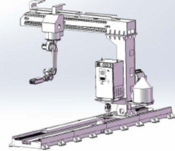
Eight-axis cantilever:
Technical characteristics of equipment (supporting)
Name: Cantilever eight-axis intelligent
workstation
Specification and model: GB-XB-2Y-10X
Total power: 18 kW
Positioning accuracy: ±0.5 mm
Eed load: 10 KG
Traveling speed: 15m/min
Walking length in x direction: track length
of 10m
Right effect length in Y direction: 2m
Maximum working range: 9*3.5*0.5 (m)
Maximum working depth: 0.5m
The cantilever eight-axis intelligent workstation is suitable for welding, cutting, grinding, and other
tasks involving steel structures such as steel beams, steel columns, equipment platform beams, equipment brackets, and box wall columns. In addition to the capabilities of the seven-axis cantilever workstation,
it has added adaptability in the single work width direction. The standard workstation can cover
workpieces with a width of 3.5 meters and a length of 9 meters.
| Name | Cantilever traveling system | Installation environment | Temperature | -10-45℃ | ||
| Model | GB-XB-2Y-10X | Humidity | 20-80% | |||
| Structure | Single machine inverted cantilever | Shock | Below 4.9m/s2 | |||
| Load | 1000KG | Other | No pyrophoric and corrosive gases, liquids; no water, oil, etc.; no close to high-intensity interference sources | |||
Positioning accuracy | ±1mm | |||||
Number of additional axles | 2 | |||||
Traveling length in X direction | Track length: 13m | Travelling speed | 8M/min | |||
| Y-axis width | 2m | It can be used to weld workpieces with a length of 12m and a width of 3.5. | ||||
Welding Power supply
Ota NBC-500RP Plus welding power supply: Digital interface control, which can directly call the welding parameters stored by customers.
The welding spatter is extremely small, and the weld seam is beautiful.
Optimized arc striking, arc stopping and ball removing functions.
Full-digital control system realizes accurate control of the welding process and stable arc length.
Powerful digital error reporting function, and various faults are displayed with error codes.
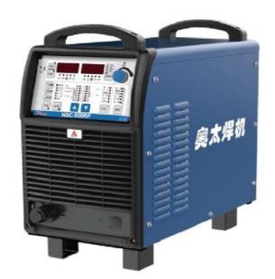
Equipment Parameters
Model | NBC-350RP | NBC-500RP Plus |
Rated input voltage/frequency (V/Hz) | Three-phase 380±10% 50 | |
Rated input capacity (KVA) | 14 | 24 |
Rated input current (A) | 20 | 38 |
Rated output voltage (V) | 31.5 | 39 |
Rated load continuous duty cycle (%) | 60 | 100 |
Output no-load voltage (V) | 101 | 106 |
Output current/voltage range (A/V) | 60/17~350/31.5 | 60/17~500/39 |
Diameter of welding wire (mm) | 0.8, 1.0, 1.2, 1.6 | |
Gas flow (L/min) | 15~20 | |
Protection level of enclosure | IP23 | |
Insulation class | H | |
Outline dimensions L×W×H (cm) | 66×32×56 | |
Weight (kg) | 50 | 55 |
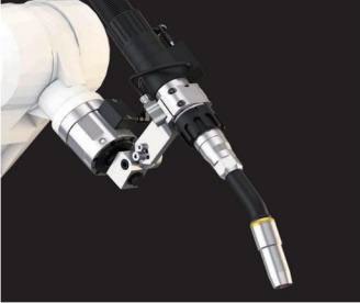
Water-cooled welding gun
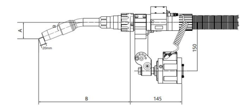
The welding gun is Terma and Apollo robot water-cooled welding gun, which is mainly composed of a water-cooled gun neck and cable. The welding gun innovatively adopts a two-way shielding gas design, which achieves an excellent gas protection effect in welding, greatly reduces the amount of shielding gas, strengthens the cooling effect of the welding gun and prolongs the service life of the contact tip.
Equipment parameters
Parameter name | Parameter |
Cooling mode: | Liquid-cooled |
Rated current value: | 500A CO2/mixed gas |
Temporary load rate of welding gun: | 100% |
Diameter of welding wire | Φ1.0~Φ1.6mm |
Optional gun neck angle: | 16°, 22°, 45° |
Optional neck length: | See the following table |
Gun neck size parameters
| a | A | B | Gun neck angle | Gun neck No. |
| 22° | 52.35 | 287.5 | 22° | TRM651W-22 |
| 22° | 52.35 | 387.4 | 22° | TRM651W-22L |
| 45° | 114.57 | 254.6 | 45° | TRM651W-45 |
| 45° | 114.57 | 354.6 | 45° | TRM651W-45L |
| 45° | 114.57 | 414.6 | 45° | TRM651W-45L1 |
| 45° | 116.6 | 554 | 45° | TRM651W-45L3 |
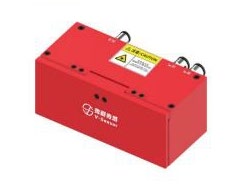
2D vision line laser
The structured light 3D camera uses MEMS coded raster structured light to scan, and reconstructs the real three-dimensional point cloud data of an object according to a binocular image restoration algorithm. Meet the 3D vision application requirements of industrial high- resolution and submillimeter measurement. The equipment has the advantages of small size, large depth of field, high measurement accuracy, low cost and simple operation. It can be applied to biometric identification, industrial automation, robots, 3D
object reconstruction and other scenarios.
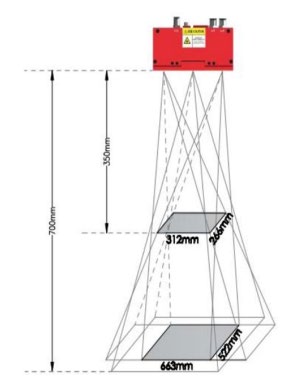
Schematic diagram of scan range
Specifications
Parameter | Haotian PDN0700 |
Light source | 850nm |
Recommended working distance | 350mm-700mm |
Near-end field of view | 260mm×312mm |
Far-end field of view | 522mm×663mm |
Z-axis accuracy | 0.1mm |
Resolution | 1280×1024 |
Acquisition time | 0.8-13s |
Scan mode | Single/continuous scan |
Triggering method | Soft |
Point cloud format | PCD, PLY, TXT |
Image type | Grayscale map, depth map |
Data interface | GigE |
Power consumption | 5.9W@12V |
Weight | 606g |
Outline dimension | 136×64×52.5mm3 |
Operating temperature | 0-50℃ |
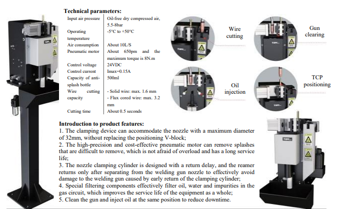
Gun cleaning station (optional):
Introduction to product features:
- The clamping device can accommodate the nozzle with a maximum diameter of 32mm, without replacing the positioning V-block;
- The high-precision and cost-effective pneumatic motor can remove splashes that are difficult to remove, which is not afraid of overload and has a long service life;
- The nozzle clamping cylinder is designed with a return delay, and the reamer returns only after separating from the welding gun nozzle to effectively avoid damage to the welding gun caused by early return of the clamping cylinder;
- Special filtering components effectively filter oil, water and impurities in the gas circuit, which improves the service life of the equipment as a whole;
- Clean the gun and inject oil at the same position to reduce
Technical Parameters
| Attribute | Value |
|---|---|
| Input Air Pressure | Oil-free dry compressed air, 5.5-8bar |
| Operating Temperature | -5°C to +50°C |
| Air Consumption | About 10L/S |
| Pneumatic Motor | About 650pm and the maximum torque is 8N.m |
| Control Voltage | 24VDC |
| Control Current | Imax=0.15A |
| Capacity of Anti-splash Bottle | 500ml |
| Wire Cutting Capacity |
– Solid wire: max. 1.6 mm – Flux cored wire: max. 3.2 mm |
| Cutting Time | About 0.5 seconds |
Functional Description:
- Clean up the splashes stuck in the gas protective sleeve of the welding gun generated by the welding robot during automatic welding operation to ensure long-term unobstructed gas, effectively block air from entering the welding area and improve weld quality;
- Clean up the dust generated by welding fume on the contact nozzle;
- Clean the gas outlet hole on the adapter pipe;
- Spray gun cleaner on the protective sleeve to reduce spatter adhesion to the nozzle and contact tube and increase durability.
- Reduce the workload of operators;
- Prevent the welding quality from being affected by inaccurate manual cleaning;
- Prevent the insulation sleeve thread between the protective cover and the main body connection pipe from wearing due to repeated manual cleaning and disassembly to prolong the operation time and reduce the cost;
- Prevent maintenance failure due to gas protection device misalignment and gas deviation caused by thread wear.
Dust removal equipment (optional)
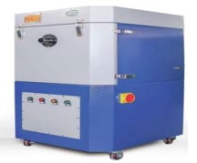
HXYD-GD300 (High negative pressure purifier)
Equipment Features:
Compact design, small footprint and easy to move.
The filter element is made of new nanofiber material, and the surface is coated with film; the smoke filtration efficiency reaches 99%
Vortex fan has the features of low energy consumption, high wind pressure, strong wind force and stable operation.
Pulse automatic dust removal, constant air pressure and thorough cleaning.
Purpose:
1. Single-station manual dual-shield welding
2. Single-station grinding and dust removal
3. Single-station robot welding
Technical Parameters
Brand name | HXYD-GD300 |
Air processing capacity | 318m3/h |
Ash removal method | Pulse ash removal |
Material of filter material | Polyester fiber + PTFE film |
Air suction port | 1 pc. |
Maximum negative pressure | 32000Pa |
Separation efficiency | 99.90% |
Filtered particles | 0.3 μm |
Motor power | 3.0Kw |
Voltage | 380V |
Filter area | 8 m2 |
Life | 5,000 hours |
Sution | Φ51mm/Φ38mm |
Length of suction arm | Customized according to customer requirements |
Outline dimensions of the machine | 620*660*1100mm |
Noise | 72±10 |
Filter cartridge brand | Import |
Ash removal method | Automatic ash removal |
Motor brand | Well-known Chinese brand |
Integrated design of gun neck dust removal (schematic diagram):

Advantages:
The dual-lumen endotracheal tube can optimize the gas circulation environment and improve the gas flow rate.
Ultra-long service life of consumables.
Better dual-channel water cooling effect.
Higher welding capacity.
The integrated design of high negative pressure dedusting equipment has a better dust removal effect and greatly reduces the possibility of interference with other equipment.
Equipment Energy Consumption
Power consumption of a single eight-axis cantilever | ||||
S/N | Equipment name | Equipment power | Quantity of single stations | Total energy consumption kW |
1 | Welding robot | 5 | 1 | 16 |
2 | Servomotor | 2 | 3 | 6 |
3 | Welder | 10 | 1 | 10 |
4 | Vision, controller | 1 | 1 | 1 |
Total |
|
|
| 33 |
Quality Control

Quality control in design stage

Quality ontrol in production stage

Quality control of installation and commissioning
Equipment quality requirements in use stage
It is generally ensured that the equipment operates normally, the accuracy of the equipment meets the use requirements, and the production takt meets the design requirements. The sub-item quality objectives are as follows:
S/N | Inspection item | Inspection method and standard | Inspection conclusion |
1 | All components are installed and tightened. | Bolts are fastened, and the network and circuit are smooth. |
|
2 | Robot performance and accuracy | Failure rate and repeated positioning accuracy during commissioning |
|
3 | Anti-collision sensor reliability | Manual simulated crash test |
|
4 | Welding machine stability | The welding output is normal and the weld formation is consistent. |
|
5 | The gun cleaning station is in normal use. | Whether the gun cleaning, wire cutting and oil injection are normal. |
|
6 | The visual system is in normal use. | The data acquisition of the visual system remains stable during the commissioning. |
|
7 | The software is in normal use. | The system drive equipment in normal use. |
|
8 |
Installation accuracy | The outline dimension deviation of equipment installation meets the design standards. |
|
9 | Appearance of equipment | The surface coating of the machined part is in good condition. |
|
10 | Brand and technical indicators of parts | The brand and technical indicators match the design selection. |
|
11 | User operation | Be able to operate the equipment normally after training |
|
Project Team

Duty responsibilities of project manager
- The first person responsible for the project, mainly responsible for controlling the project plan and overall progress, supervising the implementation of safety measures, and supervising quality control
- Participate in the preliminary business negotiations and technical communication of the project, and be responsible for purchasing material brands
- Examination of project process and bonus assessment of team members within the project team
- Timely report to the project director and project assistant about the coordination and communication of issues with Party A Customer’s supervisor
- Responsible for promoting project acceptance work and organizing and holding project summary meetings
Duty responsibilities of technical manager
- The project technical manager (control, design, process) is responsible for the feasibility of the project’s technical solutions
- Responsible for technical communication and signing of technical agreements for the project
- Responsible for optimizing technical solutions during the project process, as well as on- site commissioning and technical cooperation
Regular work meeting
|
Schedule of daily and weekly meetings on site |
|||||
|
S/N |
Time |
Time period |
Participants |
Meeting content |
Remarks |
|
1 |
Before construction in the morning |
8:00-8:30 |
All staff |
Today’s construction content: pay attention to safety points, regional leaders, and job arrangements |
The meeting time should depend on the specific situation and be chaired by the on-site project manager |
|
2 |
Before duty off in the afternoon |
17:00-17:50 |
All staff |
The completion status of today’s work plan and the arrangement of the next day’s construction content |
|
|
3 |
Every weekend |
17:00-18:30 |
All staff |
a. The completion status and existing problems of the week’s work, and propose solutions for the problems b. Conduct an early assessment of the various risks that may arise during next week’s construction |
|
|
The above are the daily and weekly routine tasks in on-site construction process management. The principle of completing the work plan is to “complete the work of the day every day” |
|||||
Plan project implementation
Plan Description
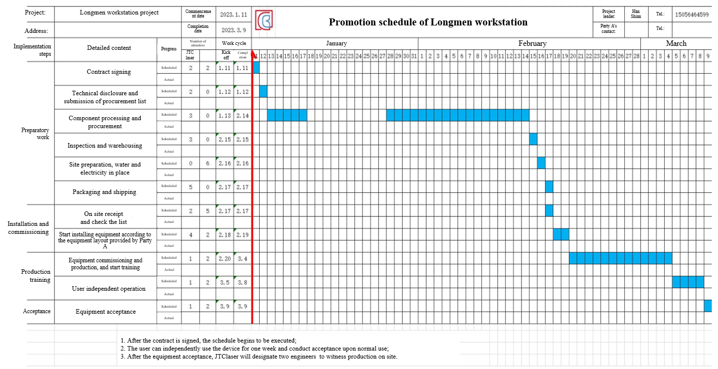
- 1 set of intelligent welding workstation is planned
- The schedule shall commence preliminary preparation work within 2 days after the contract is signed
- The entire project consists of a preliminary preparation stage, a stocking and shipping stage, an installation and commissioning stage, and a training and accompanying production stage
- Daily verification of actual progress by the project manager
- For key points, the project manager needs to organize a work meeting to analyze progress and issues during the implementation process
- After one week of independent operation of the equipment by the user, the project manager will contact the relevant departments of the user for acceptance.
Regulations on the management of safe and civilized construction sites
Preparation before entering the site
- Personnel entering the factory should receive safety and civilized construction education in advance;
- Prepare safety helmets, safety shoes, seat belts, and other necessary labor and safety equipment;
- Clarify the site and hazardous operations, and prepare fire prevention equipment;
- Confirm the number of construction personnel, shift time, and the number of personnel in each shift, and report to the on-site management personnel;
- Notify management personnel in advance of the various tools, equipment, and materials that need to be moved in, and notify the factory of the area of the stacking site for management;
Entering the site for construction
- Construction personnel wear necessary safety equipment such as safety helmets and safety shoes
- Construction personnel shall promptly clean the site and keep the construction area clean, tidy, and orderly
- Arrange the items used for construction neatly at the designated location
- Safety belts should be used when working at heights of more than 2m. Single person operation is prohibited, and there should be operators and After completing high- altitude operations, carefully inspect and do not leave any debris behind
- Follow electrician construction rules; no live construction is allowed to prevent electric shock accidents;
On site management
- After the construction is completed, the construction management personnel will inspect and confirm the project
- Construction personnel should inspect and keep the equipment and tools used well to prevent them from being scattered and left behind, causing hidden dangers
- Place various equipment, tools, and waste materials in designated locations and place them neatly
- Clean the site, passages, and entrances, restore all parts to their original state, and provide warnings for dangerous areas
Consumable Inspection List
Consumable inspection list | |||||||||
Thank you for your trust and attention to our company, and I wish your business every success! | |||||||||
S/N | Product family | Product name | Model | Figure | Unit price (including tax) | Unit | Brand | Recommended replacement time | Remarks |
1 |
605W vulnerable parts | Contact tip | TRM035-02-12 | | 6.00 | Pcs | Thelma | 8-12 hrs | Trial 1.2 welding wire |
2 | Conductive nozzle holder | TRM045-03 | 46.00 | Pcs | Thelma | 1 month | |||
3 | Nozzle | TRM015-42-16c | 56.00 | Pcs | Thelma | 1 month | Adapt to different conductive nozzle holders | ||
4 |
Nozzle socket |
TRM605w-22-02-ZJ | |
220.00 |
Pcs |
Thelma | Under normal usage, it usually lasts for 3 months, except for overloading or welding damage due to lack of water | ||
5 | Insulator | TRM605w-22-01 | 12.00 | Pcs | Thelma | 15 days | |||
6 |
Bent pipe |
TRM605w-22L-A | |
1,850.00 |
Pcs |
Thelma | Normal service life 1-2 years, excluding impact damage and scalding | The degree of the gun stem is different, please confirm | |
7 | O-ring | TRM605w-22-23 | | 24.00 | Set (3 pcs.) | Thelma | 1 month | ||
8 | Wire feed soft pipe | TRM152B-12-23 | 48.00 | Pcs | Thelma | 1 month | |||
9 | Wire feed pipe joint | TRM605w-22-22 | 22.00 | Pcs | Thelma | 2 months | |||
10 | Shunt | TRM605w-22-19 | 18.00 | Pcs | Thelma | 60 days | |||
11 | Insulating disc (including screws) | TRM231-C40252 (old) | 280.00 | Pcs | Thelma | 360 days | |||
12 | Insulating disc (including screws) | TRM231-C40252 (new) | 280.00 | Pcs | Thelma | 360 days | |||
17 | Ruiniu line laser glass 1 | 26*12*1.1mm | 2.00 | Pcs. | JTClaser | ||||
18 | Ruiniu line laser glass 2 | 26*28*1.1mm | 2.00 | Pcs. | JTClaser | ||||
19 | Wire feeding tube |
Wire feeding tube | 2m | 90.00 | Pcs | JTClaser | |||
20 | 4m | 120.00 | Pcs | JTClaser | |||||
21 | 6m | 180.00 | Pcs | JTClaser | |||||
22 | Wire feeder | Wire feeder | 1.2/1.4/1.6 | 30.00 | Pcs | Ota | |||
23 |
Teach pendant | Cable | 8m | 1,200.00 | Pcs | EFT | |||
24 | Cable | 16m | 1,600.00 | Pcs | EFT | ||||
25 | Screen maintenance | TPU-13-s-65 | 1,800.00 | Pcs | EFT | ||||
26 | Teaching pendant membrane | 20.00 | Pcs. | JTClaser | |||||
27 | Camera lens | Lens | MV-LD-4-4M-G | 800.00 | Pcs | Mind Vision | |||
28 | Point laser | Communication line | 100.00 | Pcs | Chengtuo |
Quotation instructions:
- A single order of over 1000 includes shipping costs
- The quotation includes 13% value-added tax
- Delivery method according to the agreed time
- Payment method payment upon delivery
Available Information, Tools, and Accessories
Technical information
Factory inspection reports and quality certificates of main components are provided.
One copy of equipment manual, robot programming manual, robot maintenance manual (electrical, mechanical), safety operation procedures, and other related electronic documents are provided. (Paper-based documents are not provided)
Foundation drawings (to be submitted 10 days after ordering, but construction shall take effect after both parties have reviewed and approved the equipment drawings) (electronic version).
The list of spare parts includes specifications, models, names, quantities, and manufacturer names.
Accompanying tools and accessories
S/N | Name | Specification and model | Unit | Quantity | Remarks |
1 | Internal hexagonal wrench | 1.5~12 | Set | 1 |
|
2 | USB disk | 16G | Pcs | 1 |
|
3 | Slotted screwdriver |
| Set | 1 |
|
4 | Cross screwdriver |
| Set | 1 |
|
5 | Wrench | 10 inch | Pcs | 1 |
|
6 | Sharp-nose pliers |
| Pcs | 1 |
|
7 | Tape measure | 5m | Pcs | 1 |
|
S/N | Accessory specifications and models | Unit | Quantity | Manufacturer | Remarks |
1 | Conductive nozzle TRM035-02-12 | Pcs | 20 | Thelma |
|
2 | Conductive nozzle holder TRM045-03 | Pcs | 4 | Thelma |
|
3 | Sprayer nozzle TRM015-42-16C | Pcs | 4 | Thelma |
|
4 | Ground rail lubricating oil | Bottle | 2 |
|
|
5 | Visual glass | Pcs. | 40 |
|
|
Personnel Training
Requirements for Party A’s personnel: The technical personnel who receive training must have at least high school education (including high school education) and ensure the stability of the personnel. Number of trainees: 2-3 people/single workstation
Training stage and time
- During the on-site installation and commissioning stage of Party A, the technical personnel trained by Party A need to accept the arrangement of Party B and learn about equipment installation and commissioning throughout the entire process.
- After installation and commissioning, our company will provide centralized 2-3 weeks of training for the technical personnel of Party A, and assess them. A confirmation letter of the assessment results will be issued as a basis for Party A to arrange personnel.
Main training contents
- Theoretical knowledge of robots, practical programming theory and operation, daily maintenance of equipment, and troubleshooting of equipment.
- Theoretical knowledge of welding machines, practical operation instructions, daily maintenance of equipment, and troubleshooting of equipment.
- Simple theoretical knowledge of other hardware devices, practical operating instructions, daily maintenance of equipment, and troubleshooting of equipment.
S/N | Description of key training points | Planned time (day) |
1 | Equipment installation – assistance, knowing equipment structure | 3 |
2 | Equipment commissioning – learning equipment commissioning knowledge | 1 |
3 | Training on safety, maintenance, and other knowledge of workstations | 1 |
4 | Preliminary operation training for the operating system | 5 |
5 | Training on tool calibration and automatic calibration systems | 3 |
6 | Training on welding adjustment of processes, welding machines, and teaching aids | 2 |
7 | Model processing, model driven training | 4 |
8 | Daily welding quantity assurance training | 5 |
9 | Training on common fault handling | 1 |
10 | Equipment acceptance | 2 |
Acceptance and After-sales Service
Equipment warranty
- After the final acceptance of the equipment, the warranty period is generally 12 months, calculated from the date of signing the final acceptance. If the installation and acceptance cannot be carried out in a timely manner due to the reasons of Party A, the warranty period of the equipment shall be calculated from one month after the date of arrival.
- If any major components are damaged due to quality issues during the warranty period, our company promises to replace them free of charge, and then recalculate the warranty period for the During the warranty period, the seller shall provide equipment maintenance and technical support free of charge. After receiving user notification, the seller must ensure that the equipment returns to normal operation within one week.
Equipment acceptance and after-sales service
- After installation and commissioning in the user’s factory, Party A shall confirm the integrity of the entire equipment. Afterwards, the training personnel of Party B shall conduct 2-3 weeks of operation training for the operators designated by Party A, and confirm all training items one by one. After the training is completed, Party A shall organize personnel to conduct an acceptance within one week, and it shall be deemed as the final acceptance of the equipment only after being signed by the acceptance representatives of both parties.
- The company is responsible for providing free after-sales service during the warranty period Our company promises to provide a 7*24 hour response service, and we will respond to the buyer within 2 hours from receiving the service notice (phone or letter). We provide guidance and troubleshooting for any problems that arise through phone calls, emails, instant messaging devices, etc. For problems that users cannot solve on their own, our company promises that personnel will come to the user’s site for maintenance within 24 hours. After the personnel arrive at the site, it is guaranteed to solve the general equipment problems and resume production within 24 hours.
- Outside the warranty period, the company promises to provide lifelong technical support and guarantee services for the If there are related software upgrades, our company will also provide free software upgrades for the tenderer. Equipment maintenance outside the warranty period will only charge the cost of hardware materials.
- The company promises to recommend spare parts manufacturers to ensure that the tenderer can purchase high-quality and affordable consumables and spare We also reserve spare parts and consumables for the tenderer’s emergency and temporary use.
Frequently Customer Enquiry
Most frequent questions and answers about the high-precision fiber laser cutting machine
What is the maximum payload capacity of the 8-axis welding robot workstation?
The maximum payload capacity of the 8-axis welding robot workstation is not specified in the provided information.
Can the 8-axis welding robot workstation be programmed to perform different welding patterns?
Yes, the 8-axis welding robot workstation can be programmed to perform different welding patterns.
What is the maximum reach of the 8-axis welding robot workstation?
The maximum reach of the 8-axis welding robot workstation is not specified in the provided information.
Does the 8-axis welding robot workstation have built-in laser seam tracking functionality?
It is not mentioned whether the 8-axis welding robot workstation has built-in laser seam tracking functionality.
Can the 8-axis welding robot workstation be integrated with other welding equipment, such as a high-current carbon dioxide gas-shielded welding machine?
It is not mentioned whether the 8-axis welding robot workstation can be integrated with other welding equipment, such as a high-current carbon dioxide gas-shielded welding machine.
Are there any compatibility issues with the drag teaching function of the 8-axis welding robot workstation?
It is not mentioned whether there are any compatibility issues with the drag teaching function of the 8-axis welding robot workstation.
Does the 8-axis welding robot workstation have UL certification for its motors?
It is not mentioned whether the 8-axis welding robot workstation has UL certification for its motors.
Are there any stability issues with the integration of the laser seam tracking function on the 8-axis welding robot workstation?
It is not mentioned whether there are any stability issues with the integration of the laser seam tracking function on the 8-axis welding robot workstation.

