3.1 RVCManager Interface Introduction
The main interface of RVCManager consists of two parts: the Device Management Popup and the Main Operation Interface.
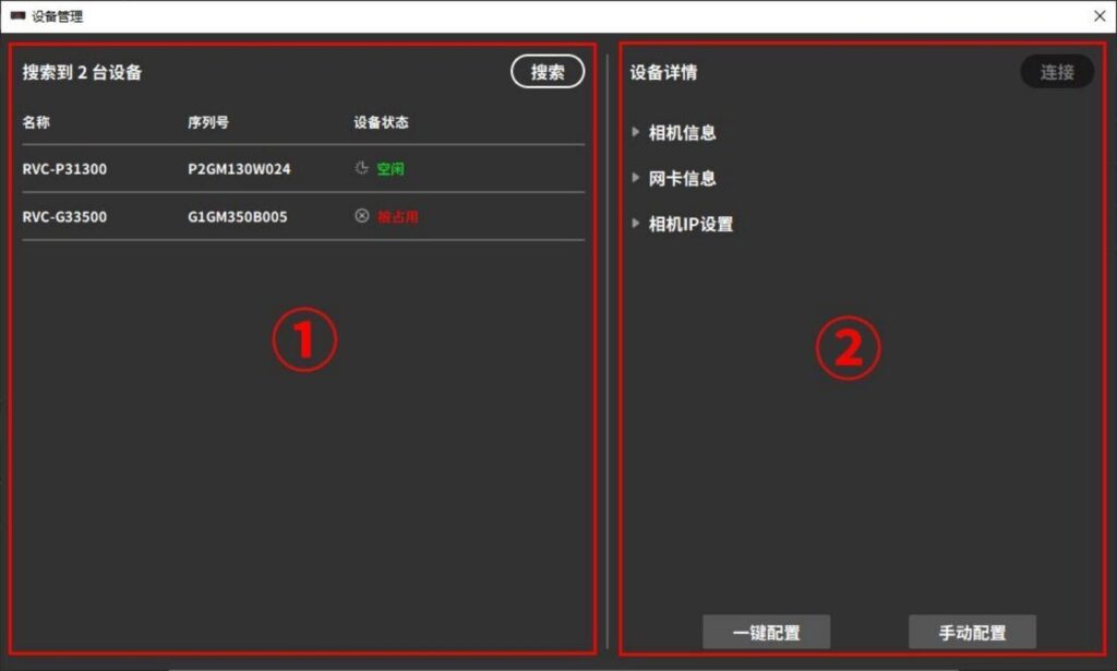
Device Management Popup
Launch RVCManager to enter the Device Management Popup.
| S# | Region | Function Description | |
|---|---|---|---|
| ① | Equipment List | Displays searchable camera names, serial numbers, and camera status. | |
| ② | Equipment Details | Camera Information | Displays basic information about the camera, including connection status, camera serial number, supported projection colors, supported shooting modes, working distance, etc. The camera serial number can be copied. |
| Network card information | Displays the network card information of the local device and the network card of the corresponding connected device (only network port cameras are visible). | ||
| Camera IP Settings | Configure the IP address of the network camera (only visible to the network camera). | ||
Main Operation Interface
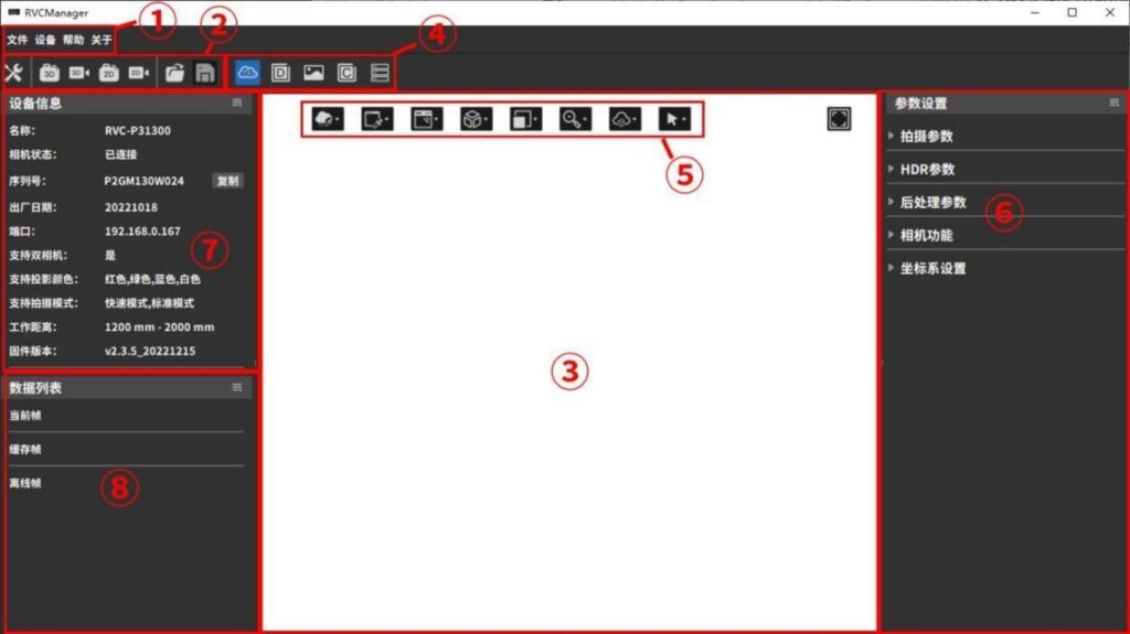
The main operation interface provides the basic functions of the software, primarily used to control the camera for data acquisition and to view the data.
| S# | Region | Function Description |
|---|---|---|
| ① | Menu Bar | Files, Devices, Help, About |
| ② | Shortcut Buttons | Device management, shooting, data import, saving, 3D point cloud/depth map/2D map/confidence map/shooting parameters |
| ③ | Content Display Area | View 3D point cloud, depth map, 2D map, confidence map, shooting parameters, offline data information, etc. |
| ④ | Content Display Switching Tab Bar | Switch the display area content type (3D point cloud/depth map/2D map/confidence map/shooting parameters) |
| ⑤ | Show Parameters Button | When the content display area displays a 3D point cloud, you can change the display parameters, such as color, data range, etc. |
| ⑥ | Parameter Setting Area | You can view and modify the current shooting parameters |
| ⑦ | Equipment Information Area | Basic information of the currently connected camera |
| ⑧ | Data List Area | List of currently cached and loaded data, you can select the corresponding display content |
For detailed descriptions of the functions and usage of each area, refer to Sections 3.2–3.5.
The functions of the top menu bar on the main interface are shown in the table below.
| Menu Bar | Submenu | Functional Description |
|---|---|---|
| document | Opening a file | Import 3D point cloud files in .ply format and preview them in the data list |
| Save the file | Export the selected preview data as a point cloud file, depth map, 2D map or cache data | |
| equipment | Device Management | Open the device management pop-up window |
| help | User Manual | Open the User Manual document |
| C++ Example | Open the C++ sample program folder | |
| C# Example | Open the C# sample program folder | |
| Python example | Open the Python sample program folder | |
| View logs | Open the log folder. If a fault occurs, you can view the log to locate the problem, or send the log to technical support. | |
| Advanced Logging | Generate an advanced log from the raw data of the camera-synthesized point cloud and open the corresponding folder. If there are quality issues with the point cloud captured by the camera, you can feedback this data to technical support |
| Menu Bar | Submenu | Functional Description |
|---|---|---|
| about | Software Information | View software version information |
| Company Information | Open the official website of Ruben Technology. You can get the latest product information, download product brochures and the latest software versions. |
SDK Documentation
For RVC SDK documentation, please refer to the docs folder under the RVCManager installation path.
Windows system: Taking the installation in the D drive as an example, the path of the RVC SDK documentation homepage is:
D:/Program Files/RVBUST/RVC/RVCSDK/docs/RVC SDK documentation.html
Linux system: The RVC SDK documentation homepage is located at:
/opt/RVC/docs/html/RVC SDK documentation.html
3.2 Camera Connection
3.2.1 Camera Connection
Before using the camera, please ensure that the cable connection is normal. If using a USB camera, the interface connected to the computer/switch should be USB 3.0; if using a network port camera, it is recommended to disable the network firewall.
Launch RVCManager, open the device management popup, and click the [Search] button to find currently connectable devices. After the search is complete, the device list area will display the names, serial numbers, and statuses of the devices found, as shown in the figure below.
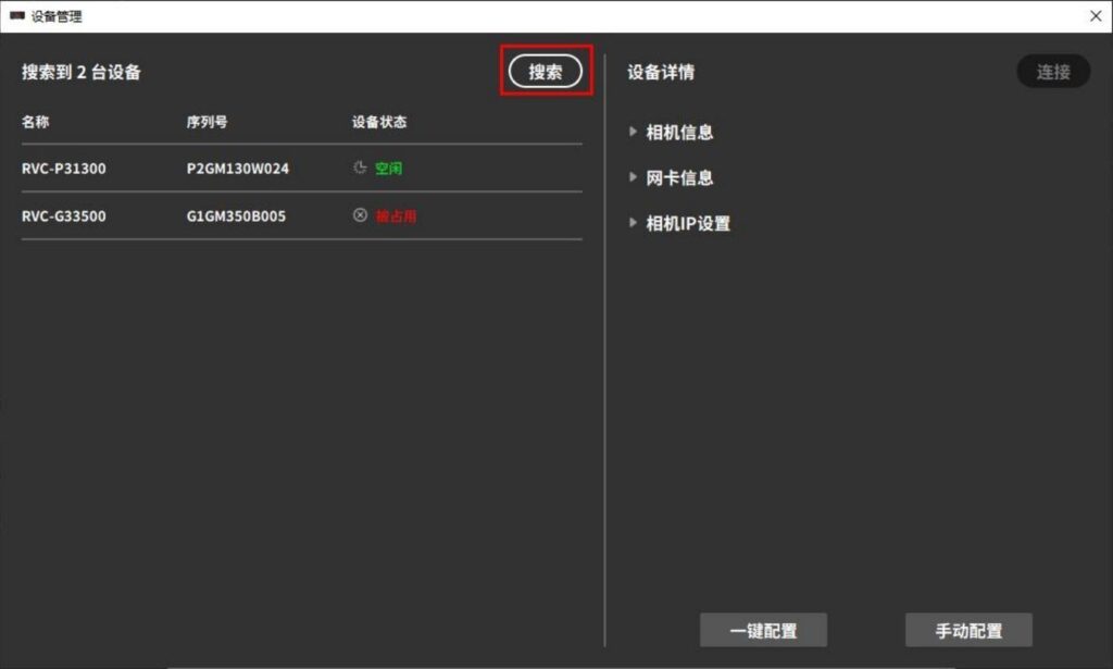
The meaning of the device status and operation suggestions are as follows:
| Device Status | Situation | Recommendations |
| idle | The camera is idle and can be connected | Select the camera and click [Connect] to complete the connection. |
| Connected | The camera is successfully connected | Ready to use |
| Occupied | The camera has been connected to another industrial computer | Check the occupied devices and search again after unoccupied. |
| Not in the same network segment | There is a problem with the network connection of the Ethernet camera | Check the network and complete the camera IP settings in the device details column |
| IP settings conflict | There is a conflict in the IP settings of the network port camera | Modify the camera IP settings in the device details column |
Attention !
When a network port camera is directly connected to the computer, the device may not be detected. In this case, a static IP needs to be configured in the system settings.
You can refer to the steps for configuring a static IP in a Linux system.
Select the camera you want to connect. If the connection is possible, the right panel of the device management popup will display the camera information. Click the [Connect] button to complete the connection.
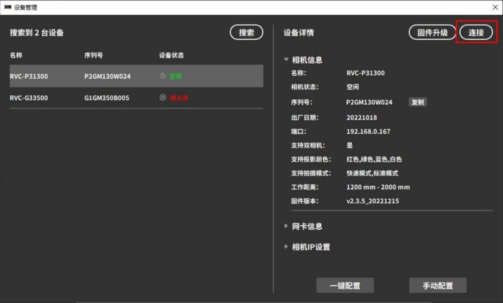
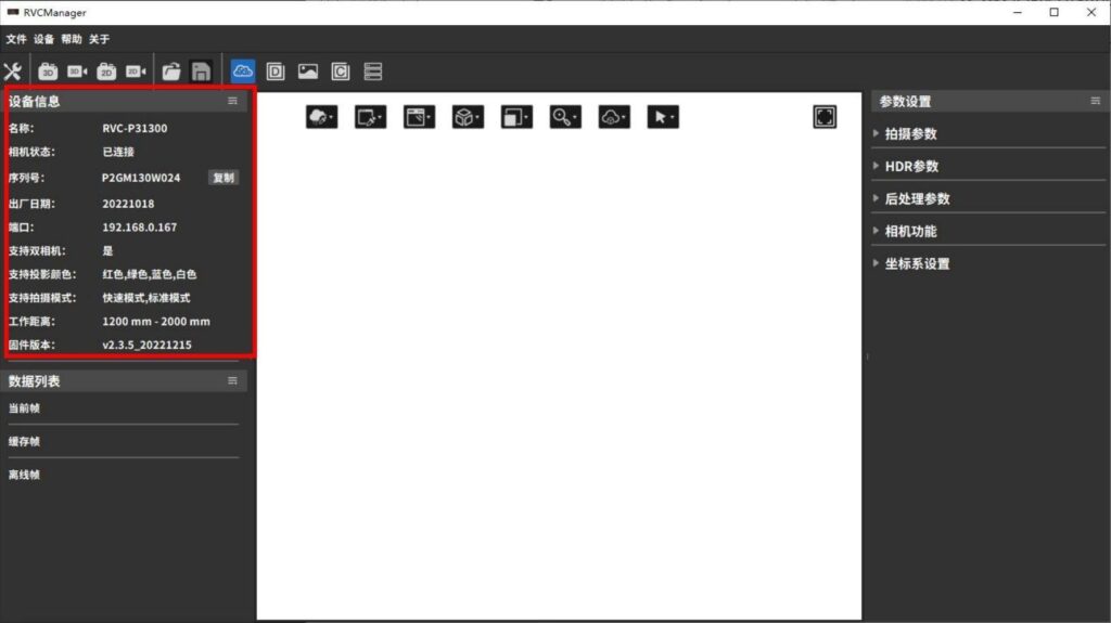
After a successful connection, the device status will change to “Connected,” the device management popup will close automatically, and the RVCManager main interface will be displayed. At this point, the camera can be used, and the device information will be shown on the left side of the main interface.
3.2.2 Set the camera IP
When the device status of the network port camera shows “Not in the same subnet” or “IP address conflict,” you need to set the camera IP before connecting. There are two ways to set the camera IP: one-click configuration and manual configuration.
One-click configuration
Select the camera for which you want to configure the IP, then click [One-Click Configuration]. The system will automatically assign an IP address to the camera and complete the network configuration.
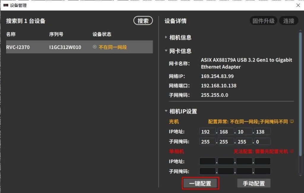
If one-click configuration fails, try manual configuration.
Manual Configuration
1. Expand [Network Card Information] to view the local network card’s IP address, port, and subnet mask.
2. Manually enter the IP address and subnet mask for the optical device and single camera (or left and right cameras).
IP address: Ensure that the entered IP addresses for the optical device and single camera (or left and right cameras) are unique and within the same subnet as the network card’s IP address.。
Subnet mask: The subnet mask for the optical device and single camera (or left and right cameras) should be consistent with the subnet mask shown in the network card information.
3. After entering the information, click [Manual Configuration] to complete the network setup.
After configuration, check whether the IP address and subnet mask settings for the optical device and single camera (or left and right cameras) are correct. The device can only connect successfully when all parts are configured properly. Refer to the figure below:
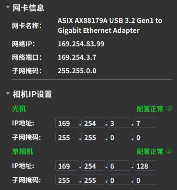
The monocular camera IP configuration is normal.
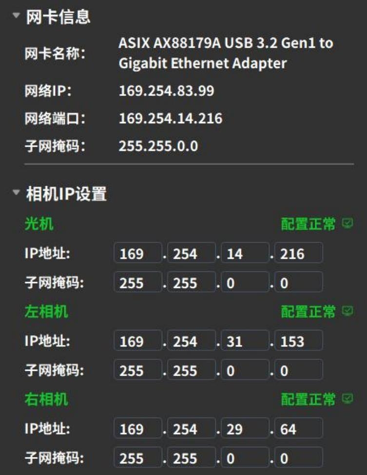
The binocular camera IP configuration is normal.
3.2.3 Firmware Upgrade
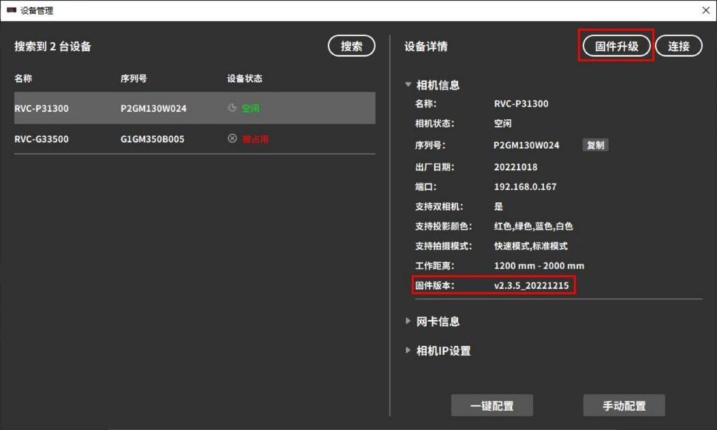
If the camera experiences hardware failure, for some devices, the hardware can be upgraded through the [Firmware Upgrade] function
Attention !
The firmware upgrade process carries risks and may cause the camera to become unusable. If an upgrade is needed, please contact technical support.