
6. WIREFEEDER
The robot dedicated welding wire feed mechanism adopts a lightweight solution, and the control part of the wire feed mechanism is placed in the welding power supply, which greatly reduces the weight of the wire feed mechanism and reduces the load-bearing burden on the robot.The wire feeding mechanism adopts four-wheel drive, and the wire feeding motor has an encoder speed feedback device, which has the advantages of high control accuracy, stable wire feeding speed, and little influence of wire feeding resistance.
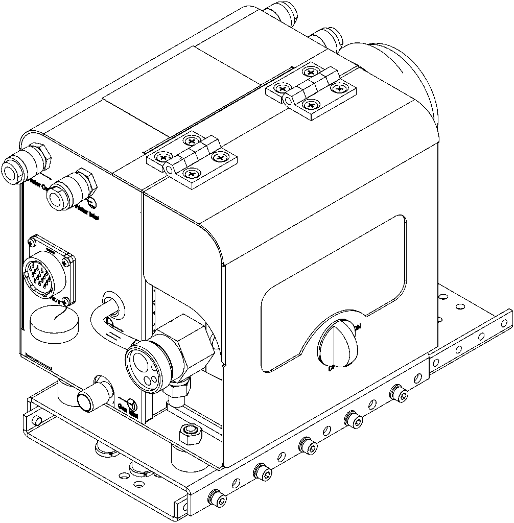
Warning! Incorrect operation may cause serious personal injury and property damage. You must read and
understand the instruction manual of this product completely before operation.
Warning! Rotating drive parts may cause personal injury. When
performing maintenance or installation work,
make sure that the drive unit of the wire feeder has stopped working.
6.1 Interface
Front panel
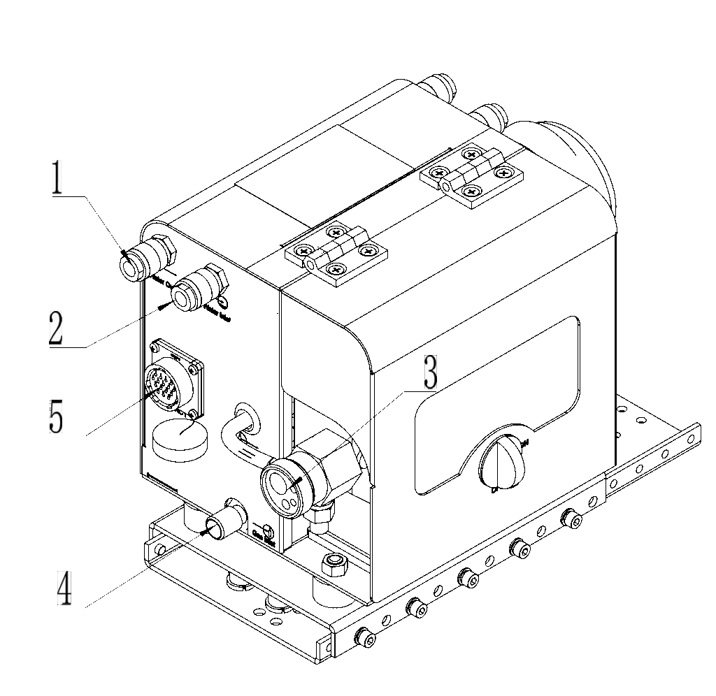

- Water outlet:connect with torch.
- Water inlet:connect with torch.
- Torch connector:connect torch and welding cable.
- Gas inlet:connect with gas regulator.
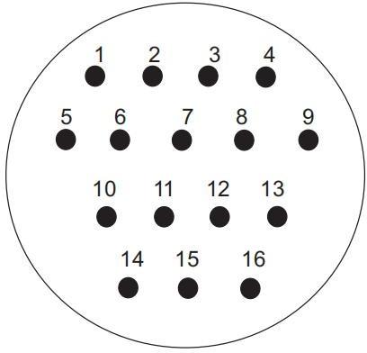
- control socket:connect with the power source, For the function of the pins, please refer to Table 6-1-1.
Fig 6-1-1 wirefeeder front panel
| No. | Description | Function |
|---|---|---|
|
||
| 1 | Solenoid valve (positive) | Solenoid valve control signal (+24VDC) |
| 2 | Solenoid valve (negative) | Solenoid valve control signal ground |
| 3 | Wire feed motor (positive) | Wire feed motor drive signal |
| 4 | Wire feed motor (negative) | Wire feed drive signal ground |
| 5 | Quick socket (positive) | Arc voltage feedback |
| 6 | Anti-collision mechanism | Anti-collision reservation signal |
| 7 | Anti-collision mechanism | Anti-collision reservation signal |
| 8 | Motor speed feedback (positive) | +5VDC power supply |
| 9 | Motor speed feedback (negative) | Ground for feedback power |
| 10 | Motor speed feedback signal output | Speed signal output |
| 11 | Gas detection switch signal | Detects gas flow (closed = valid) |
| 12 | Inch signal | Detect wire (closed = valid) |
| 13 | Trigger signal | Welder start/stop (closed = valid) |
| 14 | Common ground | Ground for gas/wire/trigger signals |
| 15 | Null | |
| 16 | Null | |
Table 6-1-1: Control Socket Pin Function Definition
Rear panel
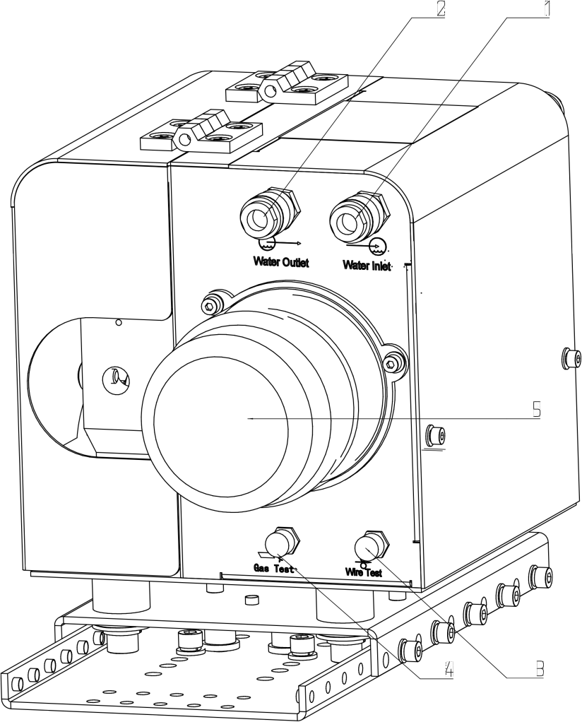
Fig 6-1-2 wirefeeder rear panel
- Water inlet:connect with water cooling machine.
- Water outlet:connect with water cooling machine.
- Wire test:Used for feeding wire when installing welding wire.
- Gas test:Detection gas flow rate before welding.
- Wirefeed Motor
Wirefeeder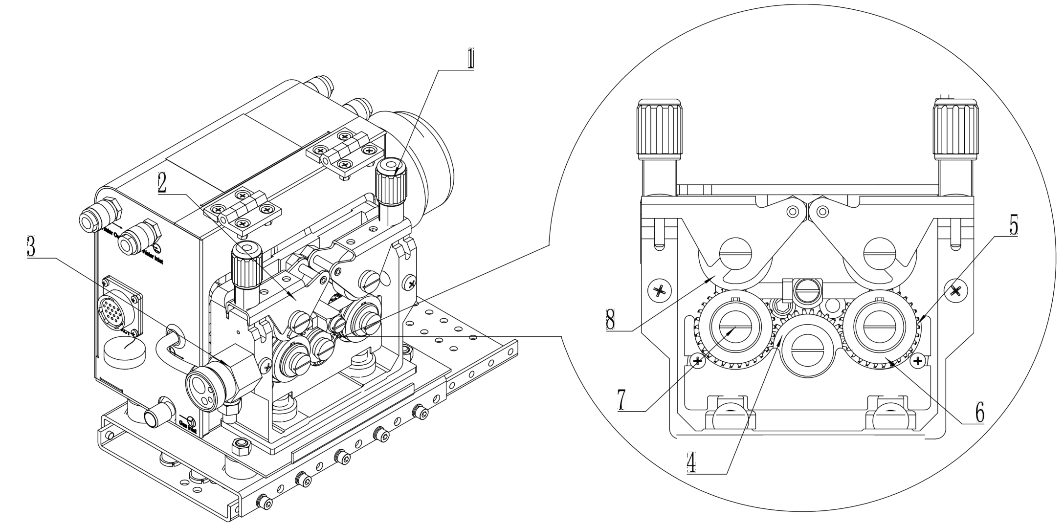
Fig 6-1-3 wirefeeder
1.Pressure handle
2.Pressure roller bracket
3.Torch connector
4.Main gear
5.Passive gear
6.Drive roller
7.Screw
8.Pressure roller
2.2 Install
Rollers
The proper wire feed rolls must be chosen according to the size and material of the wire. Types of wire feed rollers as Fig. 6-2-1:
Type 1: for hard wire, such as carbon steel wire, stainless steel wire.
Type 2: for soft wire, such as Aluminum and Aluminum alloys, also for copper and copper alloy wire.
Type 3: for flux-cored wire
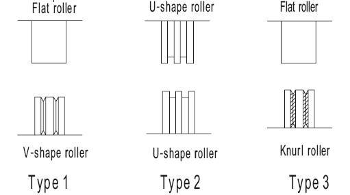
Fig. 6-2-1 Wire feed rollers
Pressure adjustment
When use pressure device to adjust wire feed roll pressure, too much pressure will cause wire crushed, and the wire coating be damaged, and it will cause the wearing out of feed rollers and increase the wire feeding resistance. Suitable pressures for wires of different materials and diameters are as shown in Fig. 6-2-2.
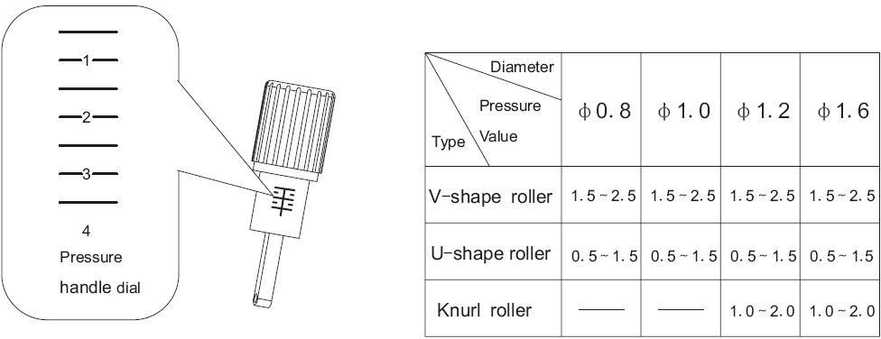
Fig. 6-2-2 Wire feed rollers installation parameter
Mounting the welding torch
To ensure normal welding, please make sure that the wire diameter, contact tip, welding torch, welding wire tube are
matched to each other.. Choose wire feeding tubes according to wires of different diameters and materials.
- Steel wire hose is suitable for hard wire, such as carbon steel wire, stainless steel wire.
- Teflon wire hose is suitable for soft wire, such as Aluminum and Aluminum alloys, also for copper and copper alloy wire.
Note!If the wire hose is too tight or too loose, it will increase resistance for wire feeding and cause wire feeding unstable.
Installation guide for steel wire hose
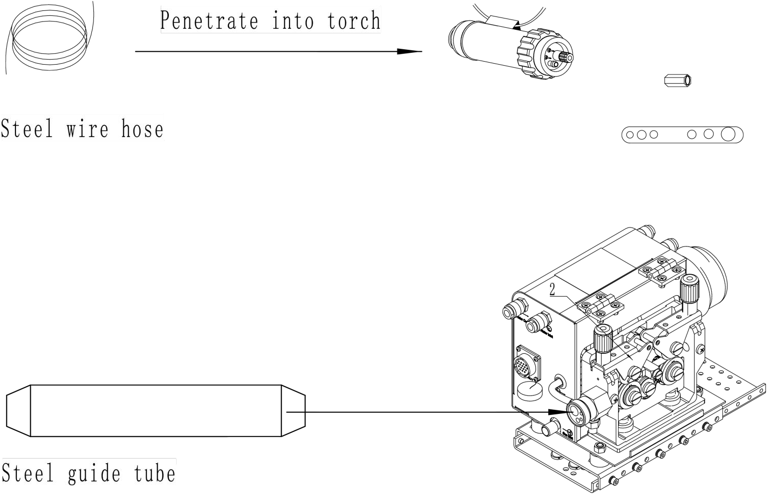
1.Replace the hoseinthetorchwith a steel wire hose.
2.Replace the guidewiretubeinthe torch connector withasteelguide tube.
3.The torch is connectedtothetorch.
Installation guide for teflon wire hose

1.Replace the hoseinthetorchwith a teflon wire hose.Thehoseisreserved for about 100-150mm.
2.Remove the steel guidewiretubefrom the torch connector.
3.The torch is connectedtothetorch connector to ensurethat theteflon hose can reachthepositionof the wire feed wheel inthefigure.