
Nine-axis cantilever workstation – Technical solution
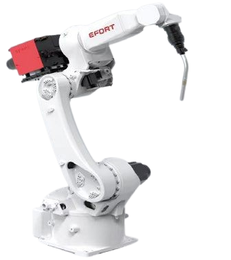
by Shaanxi Jingtai Cooperation
Laser technology Co.,Ltd
This solution is applicable to the intelligent welding of typical workpieces in the industry.
Unified description of weld analysis:
(1) Red markings indicate weldability, and yellow markings indicate non – weldability.
(2) Welds at typical parts are marked. Welds of the same type but at different parts may have their markings omitted. Other unmarked parts are not to be welded.
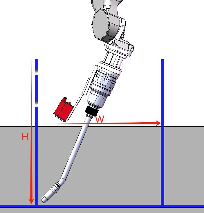
(3) The height (H) and spacing (W) of the part plates must meet the requirements in the chart. If they exceed the range, the standard welding torch cannot be used for welding.
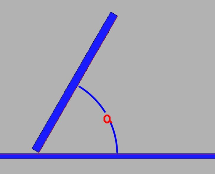
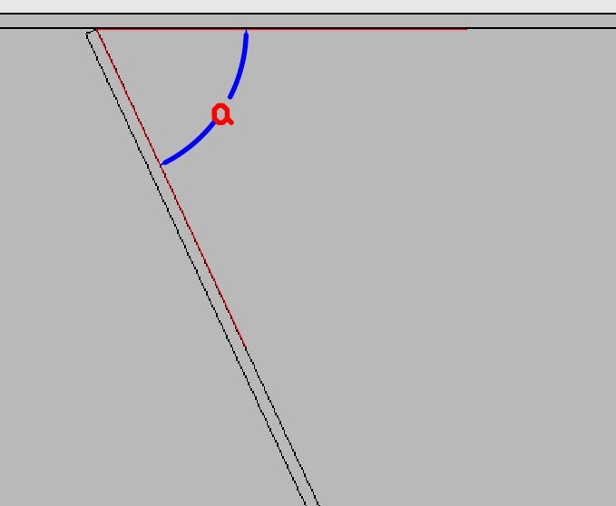
4) The included angle (tilt angle) α of the part plate should not be less than 70 degrees. If it exceeds this angle, the welding quality when the welding torch descends will be affected.
| Vertical plate height (H) | Plate spacing (W) | Specification |
|---|---|---|
| 50 | 80 | The visual recognition is on the exterior |
| 100 | 120 | The visual recognition is on the exterior |
| 200 | 280 | Includes visual recognition space |
| 300 | 340 | Includes visual recognition space |
| 400 | 420 | Includes visual recognition space |
| 550 | 500 | Includes visual recognition space |
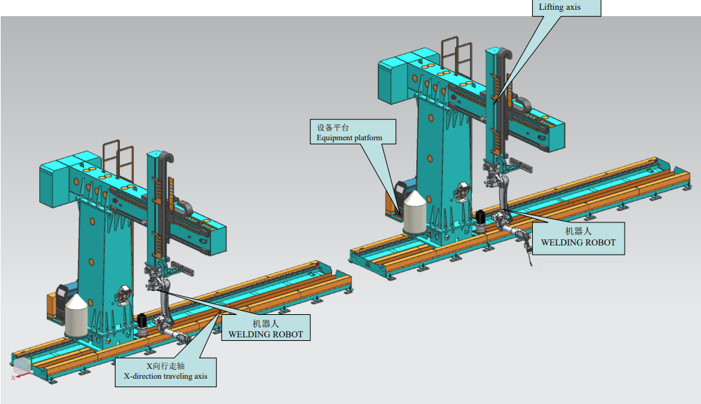
Three-dimensional schematic diagram of the workstation
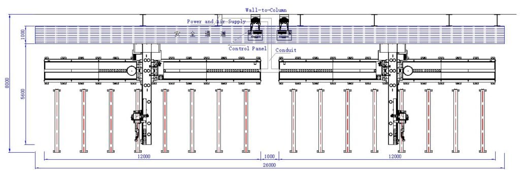
Planar schematic diagram of the workstation
Side schematic diagram
of the workstation
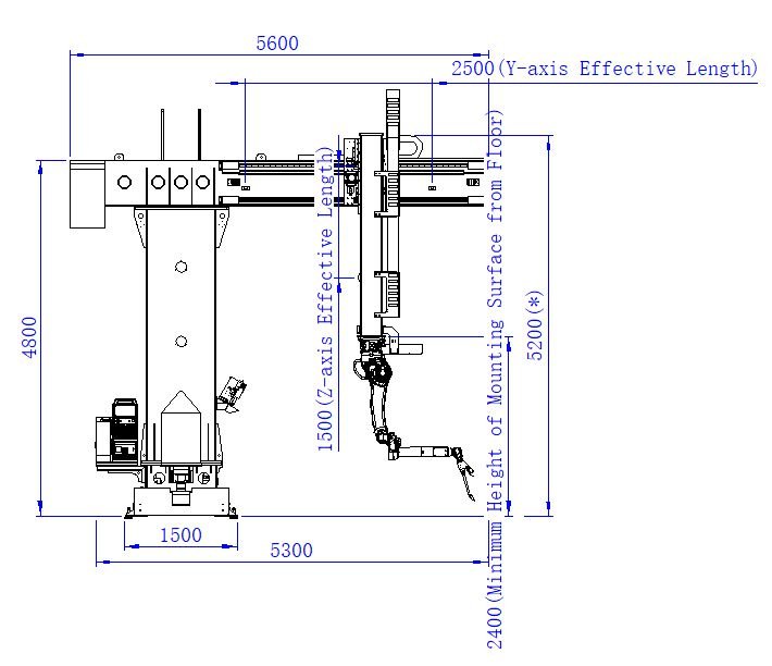
The column lowers to the minimum height:5200mm.
The column raises to the maximum height:6700mm.
Technical parameters
| The workstation covers an area of approximately | 26000mm × 8000mm | |||
|
It is suitable for the maximum workpiece size of (Width × Height, and the length is adaptable to the length of the X-axis track) |
3500mm × 1500mm | |||
| Name | Nine-axis cantilever walking system | Installation environment |
Temperature | -10 ~ 45 °C |
| Model | JTC-12X-2.5Y-1.5Z | Humidity | 20–80% | |
| Load | 500 kg | Vibration | Below 4.9 m/s² | |
| Positioning accuracy |
±0.5 mm in static state ±0.8 mm in motion state |
Other | No flammable or corrosive gases and liquids. Water and oil are not allowed. Keep away from high-intensity interference sources. | |
| Number of additional axes | 3 | |||
| Length of X-direction track | 12 m 6 m |
Maximum walking speed | 18 M/min | |
| Effective length in Y direction | 2.5 m 2 m |
Maximum walking speed | 18 M/min | |
| Effective length in Z direction | 1.5 m 1.5 m |
Maximum walking speed | 12 M/min | |
| Equipment Name | Nine-axis Cantilever Intelligent Workstation | Number of Workstations | 2 | ||||
|---|---|---|---|---|---|---|---|
| Serial Number | Sub-item | Description | Name | Unit | Quantity | Brand/Manufacturer | Remarks |
| 1 | Software System | Operating System | Intelligent Operating System | SET | 2 | OS | English Version |
| Vision System | SET | 2 | OS | English Version | |||
| Hardware Operating System | Industrial Computer/Control Console | SET | 2 | OS | |||
| 2 | Hardware Configuration | Vision Body | 3 in 1 Camera | SET | 2 | RVC-sensor | RVC-M2600 (with stand) |
| Large field Camera | SET | 2 | RVC-sensor | RVC-G52000 (with stand) | |||
| Robot System | Welding Robot | SET | 2 | KUKA | KR 16 R2010-2 | ||
| Welding Equipment | Water-cooled Welding Torch | SET | 2 | TRM | Water-cooled welding torch TRM605WHD | ||
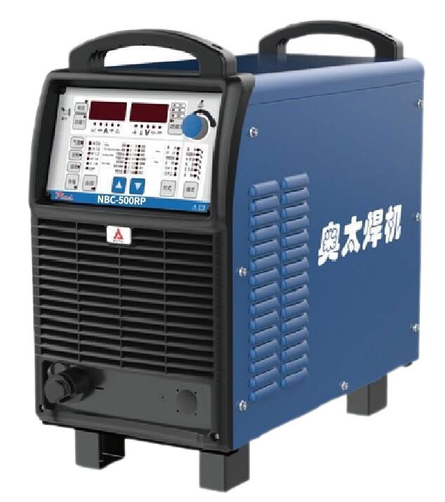
| Welding Machine | SET | 2 | Aotai | NBC-500RP Plus | |||
| Traveling System | Traveling Additional Axis | SET | 2 | Hongyi | JTC-12X-2.5Y-1.5Z | ||
| Servo Motor | SET | 2 | Kaibang | X-axis (5.5kw) / X-axis (3.14kw) | |||
| SET | 2 | Y-axis (2kw) | |||||
| SET | 2 | Z-axis (3.14kw) | |||||
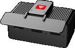
| 3 | Auxiliary Configuration | Welding Auxiliary | Welding Gun Cleaning Station | SET | 2 | TRM | SC220ASE |
Process Description:
1. Positioning and spot welding of workpieces is manually performed at Workstation 1. Then, the robot moves to Workstation 1 and conducts overall identification and reverse modeling of the workpiece through the global camera (multiple workpieces can be identified simultaneously).
2. After the system obtains the data, it generates a precise positioning program to drive the robot’s end – effector vision to conduct precise scanning in a node – based mode.
3. Once the scanning is completed, the system generates a welding program, and the robot executes the welding.
4. While the robot is working as described above, manual assembly and spot – welding are carried out at Workstation 2.
After the robot finishes welding the workpiece at Workstation 1, it moves to Workstation 2 to perform the above – mentioned welding tasks.
5. Workers transfer the welded finished products at Workstation 1 to the subsequent workstations.
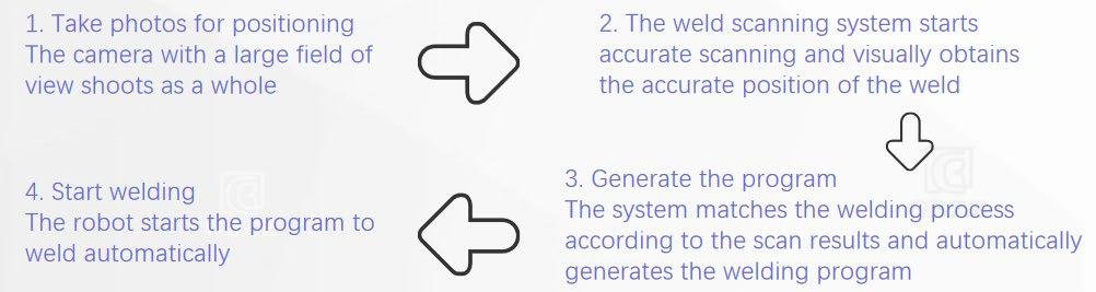
Operating System OS
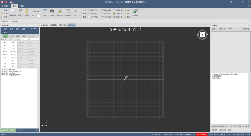
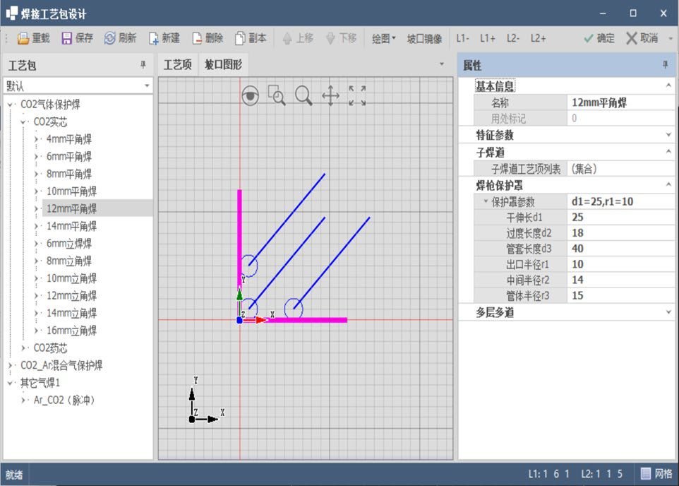
The system is completely independently developed byus. Its main function is to deeply integrate the welding process. It accurately locates the component welds through the vision system. Based on the obtained weld coordinate information, it automatically generates welding programs by integrating the welding expert database.
The software is deployed on the PC system. The PC system can be placed anywhere, and remote control of the equipment for welding can be achieved through the TCP/IP protocol.
Welding Robot – KUKA
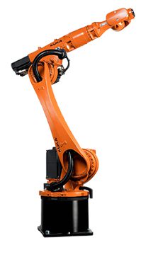
■ Rigid design endows the robot with excellent positioning ability during arc welding, and its repeat positioning accuracy can reach ±0.04 mm.
■ Based on the latest KR C5 S control cabinet ecosystem, it includes the KUKA arc welding software package and external axis product portfolio, covering process packages such as arc tracking, starting point positioning, multi – layer and multi – pass welding, laser positioning, laser tracking, and robot collaborative operation.
■ Unaffected by low temperatures, it can operate normally in the temperature range of 0 – 45°C.
■ It can be compatible with mainstream welding machines on the market to ensure communication.
■ The increase in welding speed effectively shortens the welding cycle and realizes high production efficiency.
| Technical Data Product KR 16 R2010-2 | |
|---|---|
| Specification | Value |
| Number of Axes | 6 |
| Controllable Axes | 6 |
| Work Envelope Volume | 32.5 m³ |
| Pose Repeatability (ISO 9283) | ±0.04 mm |
| Weight | 260 kg |
| Rated Payload | 16 kg |
| Maximum Payload | 19.2 kg |
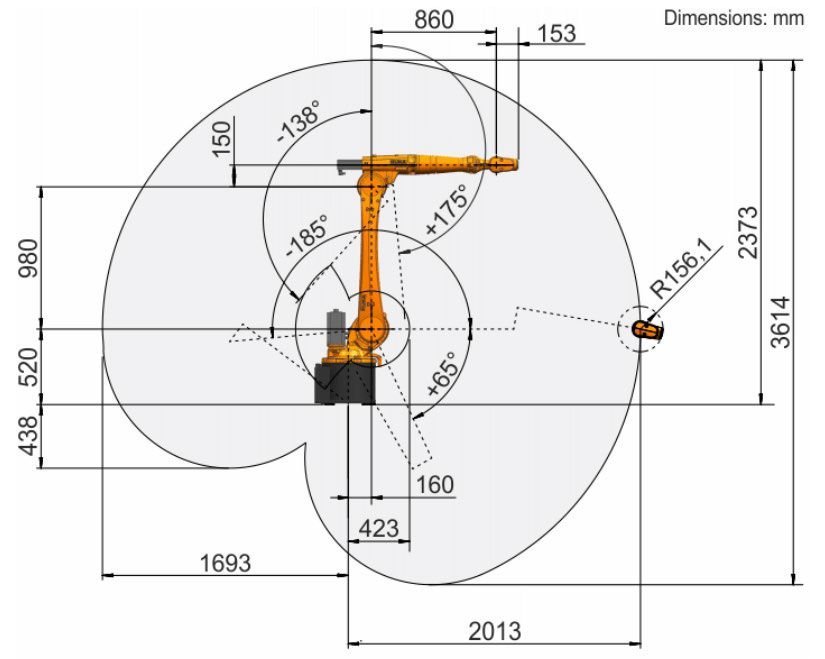
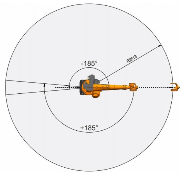
| Maximum Reach | 2013 mm |
| Protection Rating (IEC 60529) | IP65 |
| Robot Wrist Protection Rating (IEC 60529) | IP65 |
| Noise Level | <65 dB(A) |
| Installation Position | Floor; Ceiling; Wall; At any angle |
| Footprint | 430.5mm x 370 mm |
| Mounting Face Drilling Pattern | S310 |
| Permitted Tilt Angle | ±180° |
| Standard Colors | Base: Black (RAL 9005); Moving Parts: KUKA Industrial Orange (RAL 2009) |
| Controller | KR C5 S6/S7; KR C4 |
| Transformer Designation | KR C4: KR16R2010_2 C4; KR C5: KR16R2010_2 C4 |
Welding Robot – KUKA
Robot Motion Range: KR 16 R2010-2
Welding Machine – Aotai
■Functions: It has functions such as constant – voltage gas – shielded welding, manual arc welding, and large penetration. It is suitable for welding carbon steel, stainless steel, and their flux – cored wires.
■Digital Features: It is equipped with built – in digital devices like card – swiping, IOT group – control function, 485 dedicated – machine interface function, and gas flow meter. The password – based single – machine limiting function is standard – equipped, which is convenient for the management of welders not in group – control scenarios.
■New Main – circuit Design: With a new main – circuit design, the working frequency of the main circuit is increased to three times that of the basic model, and the output power is increased by 15%. This makes the root pass welding and vertical welding with small current more stable. For large – current long – cable welding, it can provide more sufficient and sustainable output power
| Serial Number | Category | NBC-500RP Plus |
|---|---|---|
| 1 | Rated Input Voltage/Frequency | Three-phase 380V ± 10%, 50Hz |
| 2 | Rated Input Capacity (KVA) | 24 |
| 3 | Rated Input Current (A) | 38 |
| 4 | Rated Output Voltage (V) | 39 |
| 5 | Rated Duty Cycle (%) | 100 |
| 6 | Output No-load Voltage (V) | 106 |
| 7 | Weight (Kg) | 55 |
| 8 | Output Range (A/V) | 60A/17V~500A/39V |
| 9 | Wire Diameter (mm) | 0.8/1.0/1.2/1.6 |
| 10 | Gas Flow Rate (L/min) | 15~20 |
| 11 | Enclosure Protection Class | IP23 |
| 12 | EMC Emission Class | A |
| 13 | Insulation Class | H |
| 14 | Overall Dimensions L×W×H (mm) | 660×320×560 |
Welding Torch – Therma TRM605WHD
The welding torch is a Therma robotic liquid – cooled welding torch, mainly composed of a liquid – cooled gun neck and cables. Innovatively, the welding torch adopts a two – way shielding gas design. This design results in an excellent gas shielding effect during welding. Meanwhile, the consumption of shielding gas is significantly reduced. The cooling effect of the welding torch is enhanced, which extends the service life of the contact tip.
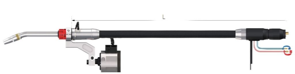
| TCP Data | |||||
|---|---|---|---|---|---|
| a | A (mm) | B (mm) | Gun Neck Angle | Gun Neck Model | |
| 22° | 44.3 | 392.63 | 22° | 550WTE51-22L341H023 | |
| Technical Parameters | |||||
| Parameter Name | Parameter Value | Other Instructions | |||
| Cooling Method | Liquid-cooled | The gun neck is replaceable. The welding torch has a built-in water-stop function for easy replacement and maintenance. | |||
| Rating | 550A CO₂ / 500A mixed gas (80%Ar + 20%CO₂) | Anti-collision function is standard | |||
| Duty Cycle | 100% | — | |||
| Wire Diameter | φ0.8 – 1.6mm | — | |||
| Gun Neck Angle | 22°, 36°, 45° | Gun necks with multiple angles and lengths are available | |||
Vision – Ruban Tri – in – one Camera
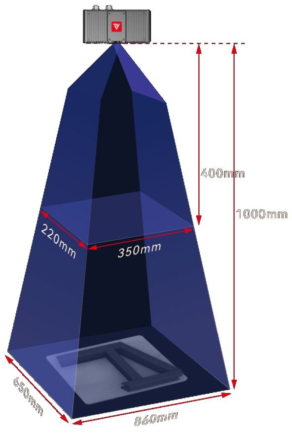
The RVC – M2600 3D camera utilizes self – developed structured – light core components and an innovative ambient – light – resistant algorithm, enabling it to image facing welding arcs and the sun. By applying a binocular dynamic compensation algorithm, it can obtain high – quality point clouds even under near – specular reflection conditions. It features strong resistance to ambient light interference, dual – mode shooting of line – scan and area – array, and is stable and easy to use. It is suitable for scenarios such as metal welding, outdoor inspection, polishing, sheet – metal spraying, loading and unloading.
| Product Reference Data | ||
|---|---|---|
| Basic Data | Camera Dimensions (mm) | 148 × 73.5 × 73.5 |
| Camera Weight (kg) | 0.95 | |
| Baseline Length (mm) | 93 | |
| Camera Resolution | 1440 × 1080 (1.6M), binocular, grayscale | |
| Light Source | Laser | |
| Data Interface | Gigabit Ethernet | |
| Operating Voltage / Current | DC 24V / 2A | |
| SDK – supported Systems | Linux / Windows | |
| SDK – supported Languages | C / C++ / C# / Python | |
| Performance Parameters | Working Distance (mm) | 400 – 1000 |
| Depth of Field (mm) | 600 | |
| Near-field of View (mm) | 350 × 220 @ 400 | |
| Field of View at Optimal Working Distance (mm) | 600 × 450 @ 700 | |
| Far-field of View (mm) | 860 × 650 @ 1000 | |
| Z – single-point Repeatability Accuracy (mm) | 0.27 @ 1000 | |
| Z – area Repeatability Accuracy (mm) | 0.05 @ 1000 | |
| XYZ Spatial Measurement Error | Full FOV < 0.2% Center FOV < 0.1% |
|
| Point Spacing (mm) | 0.25 @ 400 0.7 @ 1000 |
|
| Shooting Time (s/frame) | 0.98 – 2.26 | |
| Stability | Enclosure Protection | IP65 protection level |
| Ambient Light Resistance | Line-scan mode > 400,000 Lux | |
| Operating Temperature | -20 – 50 ℃ | |
Vision – Ruban Global Camera
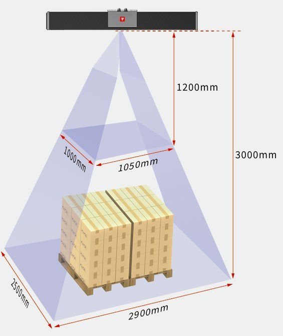
The RVC – G52000 super – large field – of – view 3D camera features a super – large field of view of 2.9×2.5×3m, a large depth of field of 1.8 meters, sub – millimeter – level accuracy, good point – cloud stability, IP65 – level protection, and excellent ambient – light – resistance performance. It can quickly measure various objects such as closely stacked and disorderly placed cartons, sacks, steel – plate workpieces, etc., and output complete and accurate high – quality 3D point – cloud data. It is widely applicable to typical palletizing and depalletizing, as well as handling scenarios in logistics, express delivery, heavy – industry machinery, etc.
| Product Reference Data | |
|---|---|
| Model | RVC-G52000 |
| Shortest Shooting Time (seconds/frame) | 1.7 |
| Resolution | 2448×2048 (5MP), binocular, grayscale |
| Working Distance Range (mm) | 1200-3000 |
| Near Field of View (FOV) (mm) | 1050×1000@1200 |
| Far Field of View (FOV) (mm) | 2900×2500@3000 |
| Resolution in XY Direction (mm) | 0.5-1.2 |
| Z-axis Single-point Repeatability Accuracy (mm) | 0.39 |
| Z-axis Area Repeatability Accuracy (mm) | 0.01 |
| Light Source | Laser |
| Communication Interface | Gigabit Ethernet |
| Camera Weight (kg) | 2.9 |
| Camera Dimensions (mm) | 692×93.5×81 |
| Operating Voltage / Current | DC24V/3.75A |
| Protection Level | IP65 |
| Operating Temperature (℃) | 0~45 |
| Operating Humidity (%RH) | 20 – 80 (no condensation) |
| Standard Accessories | Power adapter, power cord, data cable |
| Support for Third-party Development | Yes |
| Supported Programming Languages | C/C++/C#/Python |
| Supported Development Platforms | Linux/Windows |
| Compatible Third-party Software Libraries | Halcon/OpenCV/Open3D/PCL/VisionPro |
Welding Torch Cleaning Station – TERMA
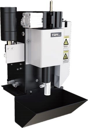
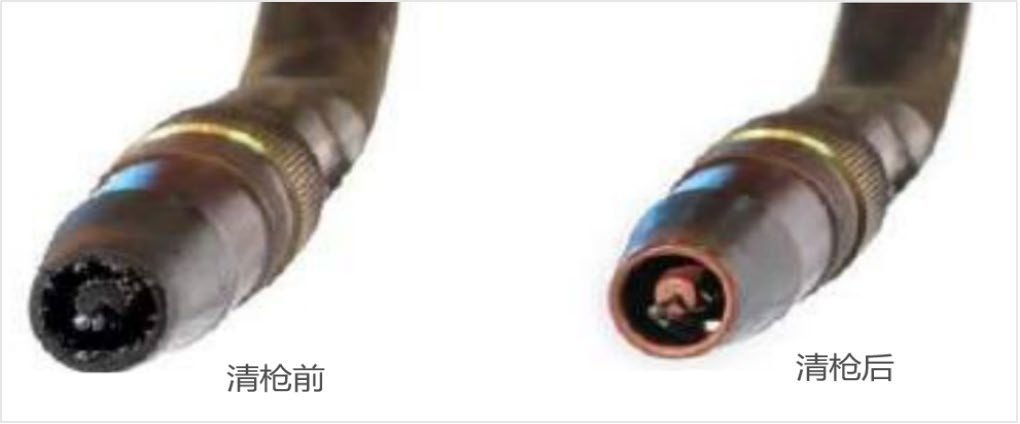
This cleaning station is designed to remove spatters that adhere and clog the gas shield sleeve of the welding torch during the automatic welding operation of the welding robot. By doing so, it ensures the long – term unobstructed flow of gas, effectively blocks air from entering the welding area, and improves the quality of the weld seam. It also cleans the dust generated by welding fumes on the contact tip and the gas outlet holes on the connecting pipe. Additionally, it sprays torch – cleaning agent onto the gas shield sleeve to reduce the tenacious adhesion of welding slag to the nozzle and the contact tip, thereby increasing their durability.
This significantly reduces the workload of operators. It prevents the situation where untimely manual cleaning affects the welding quality. Moreover, it avoids the wear of the insulating cylinder threads between the gas shield sleeve and the body connecting pipe caused by repeated disassembly and assembly during manual cleaning, thus extending the service life, reducing costs.
It also prevents the gas shield sleeve from being installed obliquely due to thread wear, which could lead to gas deflection and ultimately cause the failure of gas protection.
| Serial Number | Parameter Name | Parameter Description |
|---|---|---|
| 1 | Pneumatic Welding Torch Cleaner SC220ASE | Matches with industrial welding torches, removes spatters and trims excess welding wire. |
| 2 | Anti-spatter Liquid SC221A-PS | Contains 250 ml of anti-spatter liquid. |
| 3 | Wire-cutting Blade SC200A-JS | Cuts off the ball formed at the front end of the welding wire. |
| 4 | Industrial Reamer ANC1511-40 | Removes spatters. It is applicable for a spray nozzle with an inner diameter of 16 mm and a contact tip with an outer diameter of 10 mm. |
| 5 | Input Air Pressure | The air pressure should reach over 0.6 Mpa. |
| 6 | Air Consumption | Approximately 10 L/S. |
| 7 | Pneumatic Motor | Rotates at about 650 rpm, with a maximum torque of 8 N·m. |
| 8 | Control Current/Voltage | 24VDC / Imax = 0.15A |
| 9 | Wire-cutting Time | Approximately 0.5 seconds. |
| 10 | Wire-cutting Capacity | For solid-core welding wire, the maximum diameter is 1.6 mm; for flux-cored welding wire, the maximum diameter is 3.2 mm. |
45-foot High Cube Container Dimensions (Open Top)
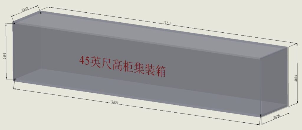
| Container Type | Internal Dimensions (L × W × H) | External Dimensions (L × W × H) | Volume | Tare Weight |
|---|---|---|---|---|
| 45ft High Cube | 13556 mm × 2352 mm × 2698 mm | 13716 mm × 2438 mm × 2896 mm | 86 m³ | 4800–5000 kg |
Structural form: H-beam, plate-rib unit, partition unit
Packing Simulation Instructions
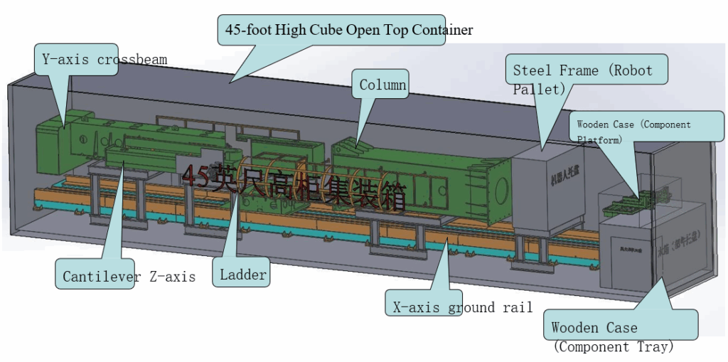
Structural form: H-beam, plate-rib unit, partition unit
Simulation description of ground rail, crossbeam, cantilever, column, ladder, and robot steel frame
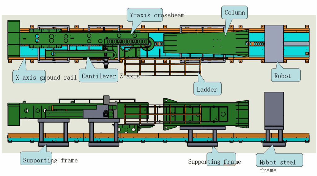
Structural form: H-beam girders, plate rib modules, and partition module
Component platform dimensions:
Inner wooden case dimensions: 1660 × 800 × 410 mm
Outer wooden case dimensions: 1700 × 860 × 580 mm
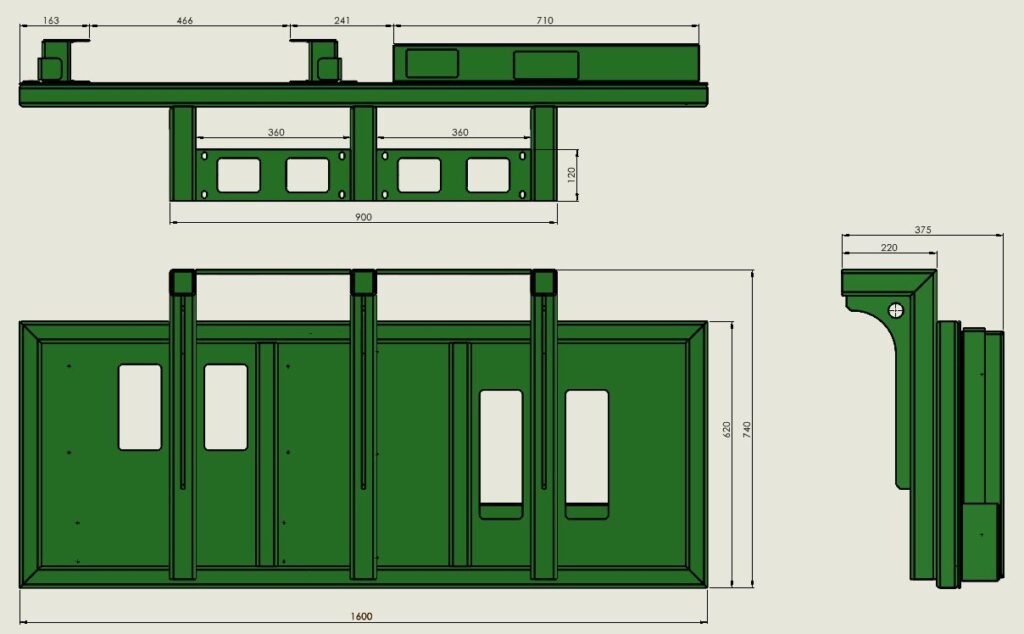
Structural form: H-beam, plate rib unit, partition unit
Column Dimension Description
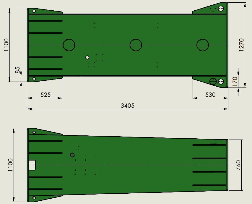
Structural form: H-beam, plate rib unit, partition unit
Crossbeam Dimension Description
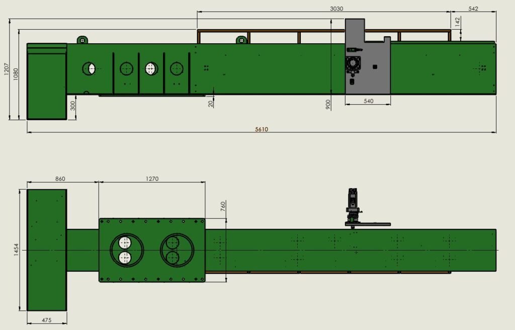
Structural form: H-beam, plate rib unit, partition unit
Robot Pallet Dimension Description
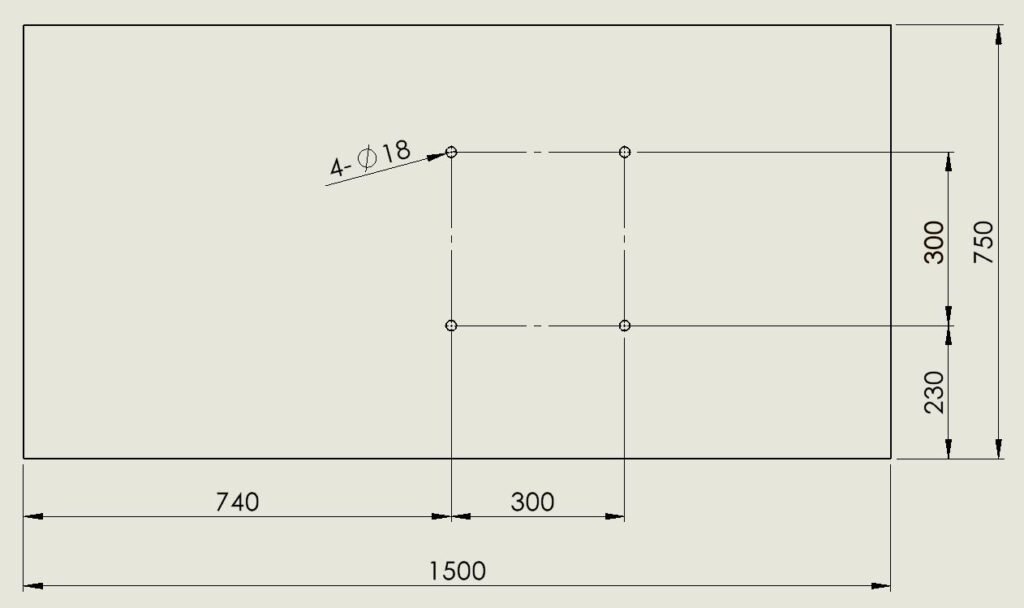
Structural form: H-beam, plate rib unit, partition unit
Component Tray Simulation Description
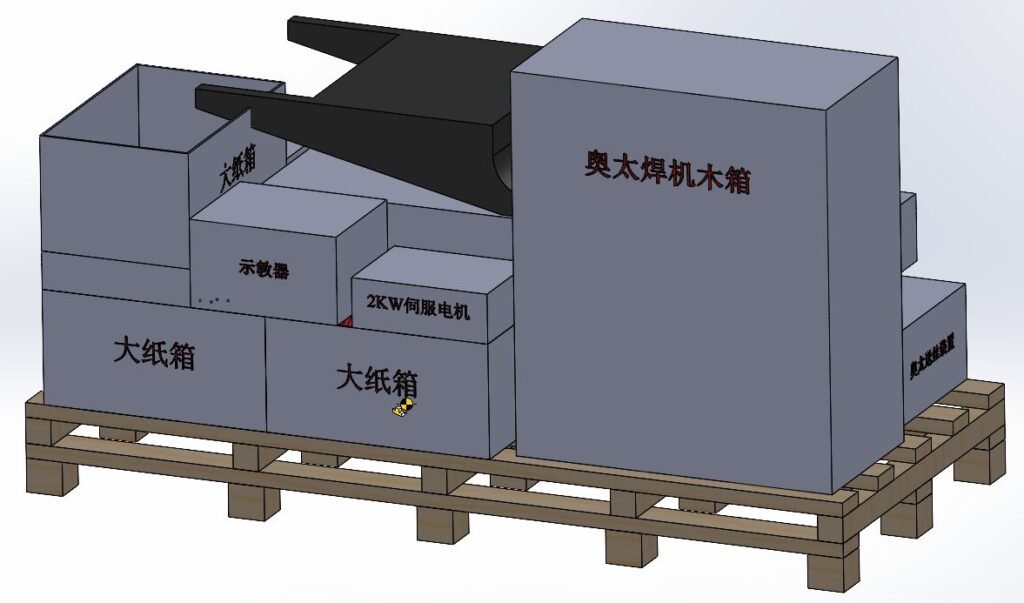
Structural form: H-beam, plate rib unit, partition unit
Component Tray Simulation Description
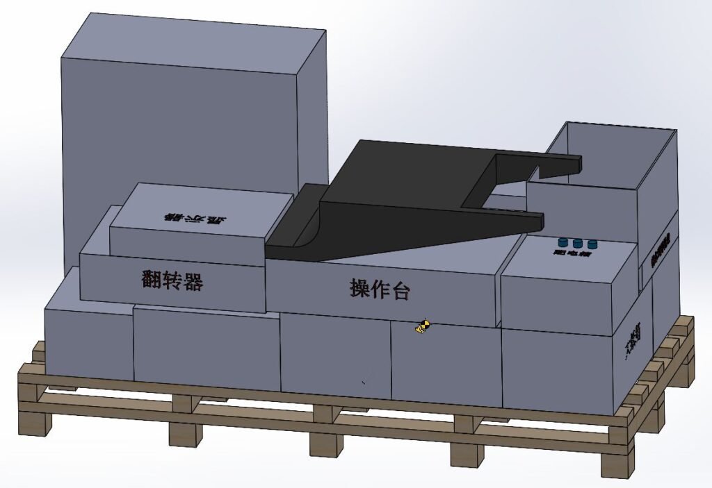
Structural form: H-beam, plate rib unit, partition unit