2. Camera Installation
The RVC camera installation process is divided into two parts: hardware installation and RVC SDK download and installation.
2.1 Hardware Installation
Installation Steps
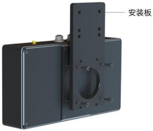
- Use screws to fix the mounting plate to the camera housing, referring to the schematic diagram.
- Secure the mounting plate to the desired installation position and tighten the screws.
- Connect the cables.
- For USB cameras: Insert the cable connector into the USB 3.0 port of the computer/industrial PC.
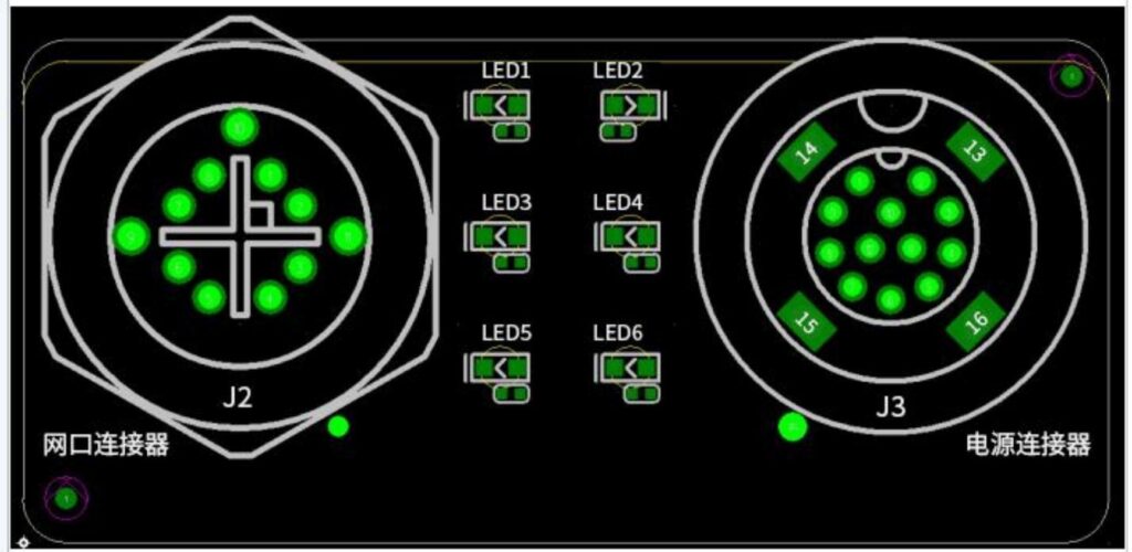
- For network cameras: Insert the cable connector into the network port of the computer/industrial PC.
- Plug the power cable into a three-prong socket to complete the installation.

Installation precautions
- The mounting plate and screws can be optionally selected according to requirements. For details, please contact customer service.
- The camera is calibrated before leaving the factory. During installation, do not disassemble the camera, adjust the lens focus ring, or move the camera angle, as this may affect the imaging quality.
- When the camera is mounted on a robotic arm or other moving device, the DC power cable and communication cable connected to the camera must be securely fixed to prevent damage from pulling or tugging on the cables or connectors.
- When connecting a USB camera to a computer, ensure the port is USB 3.0.
- The network configuration methods of Ethernet port cameras include LAN connection and camera direct connection.
LAN connection: The camera is located in the LAN where the computer is located, or the camera is connected to the LAN through a switch.
Camera direct connection: The camera is directly connected to the computer via an Ethernet cable, or connected to the computer via an Ethernet cable-USB adapter.
- When connecting, please turn on the power last.
- After the connection is completed, you can observe the direction of the camera’s light projection to avoid light being blocked.
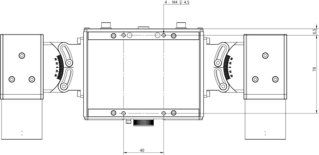
Camera installation hole diagram
The mounting holes of RVC series cameras are divided into 3 categories.
- This type of hole position is commonly used in RVC-P series/I series/X series.

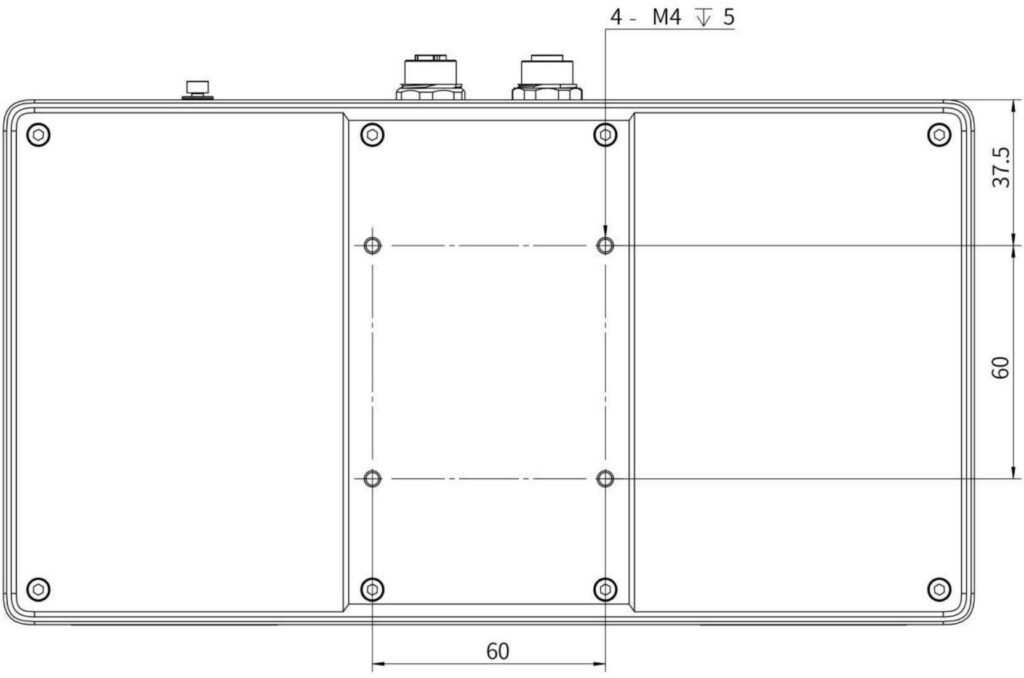
- These holes are suitable for RVC-G series laser cameras.

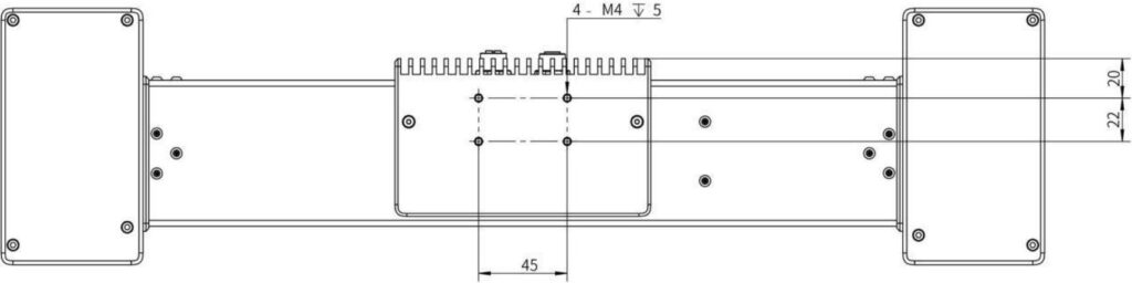
- These holes are only used for RVC-X mini.

2.2 Check the connection
After powering on, if the camera is connected properly, the projector will display the Ruben Technology logo, and the LED indicator near the camera cable interface will light up. Refer to the table below for the status of each indicator light to check whether the cables and network connections are normal.
Position No. | Color | Function | Status Description |
LED1 | orange | Data transfer rate indicator | Steady on: Data transmission is less than 1000Mbps Off: Data transmission is normal or no data transmission |
LED2 | blue | Photo status indicator | Long light: The camera is in standby mode. Blinking: The camera is shooting. Off: Camera abnormality |
LED3 | green | Ethernet port/USB cable connection indicator | On: The network cable/USB cable connection is normal Off: The network cable/USB cable connection is abnormal |
LED4 | green | Power indicator | Steady on: Power input is normal Off: Power is not connected or the power supply is faulty |
LED5 | blue | Function expansion reserved | / |
LED6 | blue | Function expansion reserved | / |
2.3 Software Download and Installation
System Requirements
Recommended Configuration | Minimum Requirements | |
System | 64-bit Windows 10/Debian 10 and above | 64-bit Windows 10 / Debian 9 / Ubuntu 16.04 |
Processor | Intel i7 | Intel i5 |
RAM | 64 GB | 16 GB |
HDD Space | 32 GB | 8 GB |
Network card configuration requirements
Recommended Configuration | Not Recommended Configuration |
Intel chip PCIE Gigabit network card (electrical port, copper cable), such as Intel I350 chip, Intel 82571, 82545, 82576 chip, etc. | Realtek full range of network cards, some Intel chip network cards (such as Intel 82574L, Pro/1000PM, etc.) |
Other chips not listed are mainly based on actual testing | |
RVCManager Software Download
Please contact technical support or sales personnel to obtain the latest RVCManager installation package download information. You can also visit Ruben Technology’s official website at http://rvbust.com/download.html to download the installation package compatible with your system.
If you are using RVCManager for the first time, please refer to the installation guide to complete the software installation.
If you have already installed RVCManager, it is recommended to completely delete the SDK folder and related files before reinstalling when updating the software version, to avoid installation failures.
Installation Package Naming Convention
The naming convention for the RVCManager installation package in the Windows environment is:
RVCSetup (version number) (release date) (installation type).exe
The naming convention of the RVCManager installation package in Linux environment is: RVCSetup (version number) (release date) (installation type).deb
For versions with “cuda” in the installation type, NVIDIA graphics card and CUDA environment are required.
Installation Steps
Windows system: Double-click the installation package file and follow the instructions to complete the software and driver installation.
Linux system: Enter the file path where the installation package is located and execute the following command to complete the software installation. Please modify the command content according to the name of the downloaded installation package version.
sudo dpkg -i RVCSetup-(version number)-(release date)-(installation type).deb
For common installation problems, please see Post Common Problems and Solution - 4.3.


