5. AMIG 500 PR PLUS
5.1 Interface
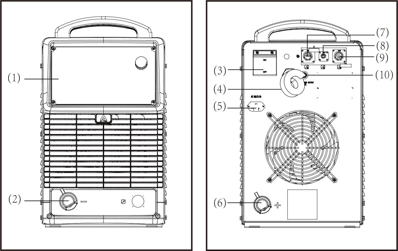
- Control panel
It is used for function selection and some parameter settings. The control panel includes a digital display window, adjustment knobs, buttons, and LED indicators. - Quick socket (-)
For connecting with the work piece by ground cable. - Circuit breaker
The function of the circuit breaker is to protect the welding machine and operator by automatic trip to turn off power supply when overload or short circuit happens to the power source. Normally, the switch flipped upward means power-on. To start or stop the welding machine is done by the mains switch in the distribution box. Please do not take this circuit breaker as the power switch. - Power input cable
Applies power to the welding power source. - Power supply socket for gas heater (AC36V)
For connecting the heater coil of the CO2 gas regulator. - Quick socket (+)
Connects with the wire feeder by wire feeder cable. - Analogue control socket X5
The analogue connector can use an analogue control cable to connect to a robot, offering low cost and high reliability. It can perform basic welding processes by robot but cannot use an expert database. Please reference the robot interface. - Digital control socket X6
The digital connector control function is powerful, with strong universality, and can match most robots in the market. However, this robot needs to have a digital communication module and requires purchasing a digital interface box from a specified vendor. - Wire feeder control socket X7
For connecting with the wire feeder of the robot; please reference the robot interface. - Overcurrent protector
Pops up when overcurrent occurs to protect the wire feeder motor.
5.2 Control panel
The functions on the control panels are all arranged in a very logical way. The various modes and parameters needed for welding are easy to select by pressing the appropriate button; parameters are easy to be adjusted by rotating the encoder. Synergic adjustment makes complicated operation much easier.
Note! Some described parameters in this manual may be slightly different from the power source, and some identification may be slightly different from power source identification, but the manner of working is the same.
Warning! Operating the equipment incorrectly can cause serious injury and damage. Do not use the functions described here until you have read and completely understood all content of this manual.
Note! Control panel of welding machine is for function selection and some parameters setting.
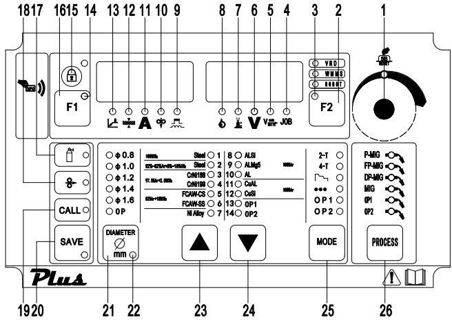
1. Adjustment knob
Adjust the parameters. When the light is on, this knob can be used to adjust parameters of the selected item.
Reset to factory setting: Press and hold adjustment knob (1) for about 5 seconds; it comes back to factory setting.
Important! Values increase in clockwise direction while values decrease in anti-clockwise rotation. To turn the knob left or right while pressing it will achieve quick adjustment.
2. Parameters selection button F2
Press this button, one parameter indicator light turns on, and the corresponding parameter is chosen, from right to left:
- Motor current display
- Arc length adjustment
- Welding voltage
- Welding speed
- Job (Channel) No.
If both the indicators of the parameter selection button and the adjustment knob (1) are on, the indicated/selected parameter can be altered with the adjustment knob (1).
3. F2 selection button indicator
When the indicator light is on, the button F2 is selected.
4. Job number indicator
When the indicator light is on, for receiving parameter records/job numbers that were previously saved with the “Store” button.
5. Welding speed indicator
When the light is on, the right display shows the preset welding speed (in/min), and the wire speed and welding current & voltage are calculated as a function of the “a”-dimension parameter (20).
6. Welding voltage indicator
When the indicator lights up, the right display shows the preset or actual welding voltage.
Important! Power source open circuit voltage is variable. In STICK mode, open circuit voltage displayed is about 23V before welding; after starting arc, it increases as the real situation, and may be up to 79V, so as to get ideal arcing characteristic.
7. Arc-length correction indicator
For correcting the arc length (-5.0-+5.0) by adjustment knob (1) when the indicator is on, the right display shows the arc length value when the indicator lights up.
- – shorter arc length
- 0 neutral arc length
- + longer arc length
Important! The range (-5.0-+5.0) means that, when preset welding current, the arc length value is -50%~+50% of the corresponding welding voltage.
8. Wire feed motor current indicator
When the indicator light is on, the actual motor current is displayed.
9. Arc force/arc stiffness indicator
For adjusting the peak current during the P-MIG/MAG welding process, values range (-5.0-+5.0)
- – shorter arc length
- 0 neutral arc length
- + longer arc length
For synergic MIG, the inductance value when changing short circuiting transfer (-5.0-+5.0).
- – harder, stable arc
- 0 neutral arc
- + soft, low spatter arc
10. Wire feeding speed indicator
When the indicator is on, the left display shows the wire feeding speed (M/min); when you adjust this button, the relevant parameters will change automatically.
11. Welding current indicator
When the indicator is on, the left display shows the preset or real welding current values.
12. Sheet thickness indicator
When the indicator is on, the left display shows the preset sheet thickness (mm). The relevant parameters will change automatically when this value is changed.
13. “a” dimension indicator
When the indicator is on, the left display shows “a” dimension (mm). Wire speed and welding current & voltage are calculated as a function of the “a”-dimension parameter.
14. F1 selection button indicator
When the indicator lights up, the F1 button works.
15. Parameters selection button F1
Press this button, one parameter indicator light turns on and the corresponding parameter is chosen; keep pressing this button to switch among the following parameters:
- “a” dimension
- Sheet thickness
- Welding current
- Welding speed
- Peak current/inductance
Important! On Panel control mode, press F1 to choose one of the above parameters, and the value of the parameter can be adjusted by the knob (1).
If in remote control mode, press F1 to choose one of the above parameters, and the value of the parameter can be adjusted by the current potentiometer knob on the analog wire feeder.
16. Lock screen button
Press the button to lock the panel parameters, and press it again to unlock; long press the button for 3s to turn off the panel, and the indicator light flashes. Press it again to unlock, and the display returns to normal.
17. Gas test button
Press the button to start continuous gas supply, and the gas supply lasts for 15s; press this button again to stop.
18. Wire test button
When pressed, the indicator light lights up to start wire feeding, and the panel displays the wire feeding speed synchronously; the wire feeding stops when released.
19. CALL button
Loads a stored set of parameters.
20. SAVE button
- For accessing the sub-menu parameter set-up menu or (in job mode) for storing parameter settings.
- During creating or correcting a job, store parameter settings.
21. Wire diameter button
For selecting wire diameter.
22. Sub-menu indicator
The indicator light is on when entering the sub menu adjustment.
23. Wire material selection
Select the wire material and shielding gas to be used for welding.
24. Wire material selection
Select the wire material and shielding gas to be used for welding.
25. MODE button(s)
For selecting the operating mode of the torch.
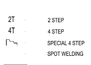
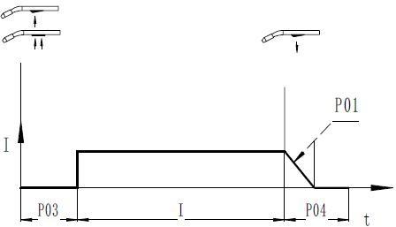
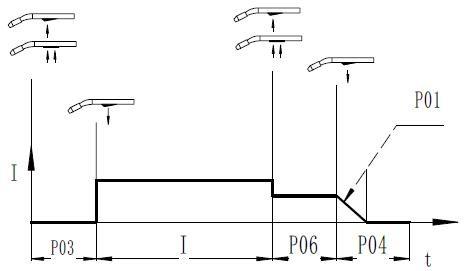
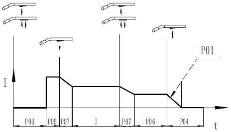
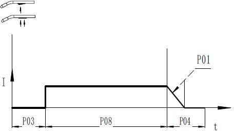
26. Operating mode of welding torch
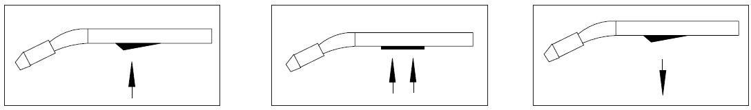
Fig. 4-3-2 Press trigger Fig.4-3-3 Hold trigger Fig.4-3-4 Release trigger
- P03……Pre-gas time
- P05……Initial parameter: The base metal can be heated up rapidly, despite the fast thermal dissipation at the start of welding.
- P07……Down-slope time: The time from welding current to crater-filler current.
- I Welding current: Uniform thermal input for the preheated base metals.
- P06……Crater-filler parameter: Prevent burn-through caused by too much heat at the welding ends.
- P08……Spot welding time
- P04……Post-gas time
- P01……Burn back time
2-step mode
4-step mode
Special 4-step mode (initial parameters and crater filler parameters are adjustable)
Spot welding mode
26. Welding mode selection button
- P-MIG: pulse MIG
- FP-MIG: fast pulse MIG
- MIG: Constant voltage mode
- DP-MIG: deep penetration MIG


