Maintenance
Only maintenance and repair work described in this document may be performed.
Work that exceeds this scope may only be carried out by personnel spe- cially trained by KUKA. Information about KUKA College and its training program can be found at college.kuka.com or can be obtained directly from our subsidiaries.
In the case of support and repair services provided by KUKA, KUKA Serv- ice must be informed in advance about potential contamination or haz- ards.
Non-compliance nullifies warranty and liability claims.
Maintenance overview
Description
The maintenance intervals given in the tables are valid for the operating conditions specified in the technical data (>>> 4 “Technical data” Page 35). KUKA must be consulted in the event of deviations in working conditions or the use of special functions or applications.
A general inspection of the manipulator is recommended after 7 years or upon modifying its use. Please contact KUKA Service for this. If the robot is fitted with a KUKA energy supply system (optional), addi- tional maintenance work must be carried out.
Notice
Only auxiliary substances and consumables approved by KUKA Deutschland GmbH may be used. Non-approved auxiliary substances and consumables may cause premature wear and failure of assemblies.
Precondition
• The maintenance points must be freely accessible.
• Remove the tools and any additional items of equipment if they impede maintenance work.
Warning
Danger to life and limb due to unintended robot motions
When carrying out the following work, the robot must be moved several times between the individual work steps. Unintentional movements of the robot can cause death, serious injury or material damage.
- While work is being carried out on the robot, it must always be se- cured by actuating the EMERGENCY STOP device.
- If work is carried out on an operational robot that is switched on, the robot must only be moved at reduced velocity. It must be possible to stop the robot at any time by actuating an EMERGENCY STOP de- vice. Operation must be limited to what is absolutely necessary.
- Warn all persons concerned before switching on and moving the ro-
If oil temperatures of more than 333 K (60 °C) are reached during operation, shorter maintenance intervals must be observed; for this, consultation with KUKA Deutschland GmbH is necessary.
Maintenance table
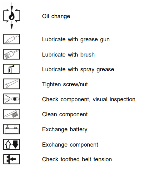
Maintenance symbols
The overview may contain maintenance symbols that are not relevant
for the maintenance work on this product. The maintenance illustrations
provide an overview of the relevant maintenance work.
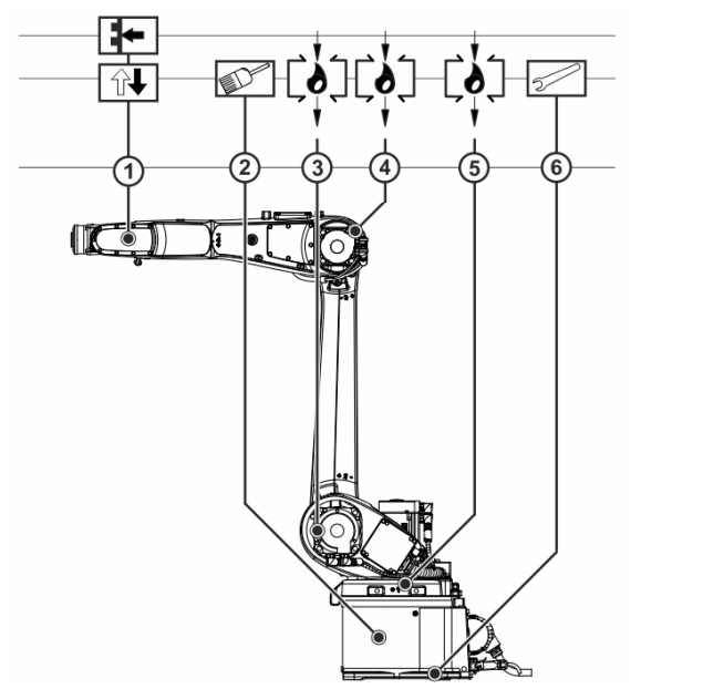
| Interval | Item | Task | Auxiliary substances and consumables |
| Once only, after 100 h | 6 | Check the tightening torque for anchor nuts and holding-down bolts. | |
| 5,000 h or 1 year at the latest | – | Carry out a visual inspection of visible flexible tubes for damage. In the case of damage and/or cracks, have the cable set exchanged by KUKA Service. | |
| 5,000 h or 1 year at the latest | 2 | Grease cable set A1 (See section 8.2 “Greasing cable set A1”, Page 164) | Lubricating grease Optitemp RB2, 200 cm³ |
| 5,000 h or 1 year at the latest | 1 | Exchange toothed belt A5 (See section 8.3 “Exchanging the toothed belt on A5”, Page 167) | |
| 20,000 h or 5 years at the latest | 4 | Oil change, gear unit A3 (See section 8.6 “Oil change in A3”, Page 185) | Optigear Synt. ALR 150, Initial filling quantity: 0.26 l |
| 20,000 h or 5 years at the latest | 3 | Oil change, gear unit A2 (See section 8.5 “Oil change in A2”, Page 181) | Optigear Synt. ALR 150, Initial filling quantity: 0.43 l |
| 20,000 h or 5 years at the latest | 5 | Oil change, gear unit A2 (See section 8.4 “Oil change in A2”, Page 173) | Optigear Synt. ALR 150, Initial filling quantity: 0.43 l |
Up-to-date safety data sheets must be requested from the manufacturers of auxiliary and operating materials. Further information about the auxiliary substances and consumables used can be found under:
Greasing cable set A1
Description
The maintenance intervals given in the tables are valid for the operating conditions specified in the technical data (>>> 4 “Technical data” Page 35). KUKA must be consulted in the event of deviations in working conditions or the use of special functions or applications.
Equipment
The following equipment is required:
| Designation | Article number |
| Set of Allen keys 1.5; 2; 2.5; 3; 4; 5; 6; 8; 10 mm | – |
| Torque wrench min. 5 Nm to 50 Nm | – |
| Socket wrench set | – |
| Set of combination wrenches 6; 7; 8; 9; 10; 11; 12; 13; 14; 15; 17; 19 mm | – |
| Brush | – |
Material
The following material is required:
| Designation | Article number | Quantity |
| Lubricating grease Optitemp RB2 | (>>> 12.2 “Auxiliary and operating materials used” Page 216) | 0.3 kg |
Tightening Torques
The tightening torques can be found under: (>>> 12.1 “Tightening torques” Page 215)
These are valid for screws and nuts where no other specifications are given. Screws of strength class 10.9 and higher as well as screws with test certification may only be tightened once with the rated tightening torque. When the screws are first slackened they must be replaced with new ones.
Precondition
- The robot is accessible in the area of axis 1.
Work Safety
The maintenance intervals given in the tables are valid for the operating conditions specified in the technical data (>>> 4 “Technical data” Page 35). KUKA must be consulted in the event of deviations in working conditions or the use of special functions or applications.
Warning
Danger to life and limb due to unintended robot motions Unintended robot motions may result in death, severe injuries and dam- age to property.
- Secure the robot by pressing the EMERGENCY STOP
- Warn all persons concerned before starting to put it back into opera-
Warning
Direct contact with cable grease may have an adverse effect on health. Wear protective gloves and personal protective equipment. The general safety instructions and the safety data sheet must be observed.
Removing the cover from the base frame
- Remove 5 M6x8-10.9-A2K round head screws from the
- Take the cover with brush fitted carefully off the base
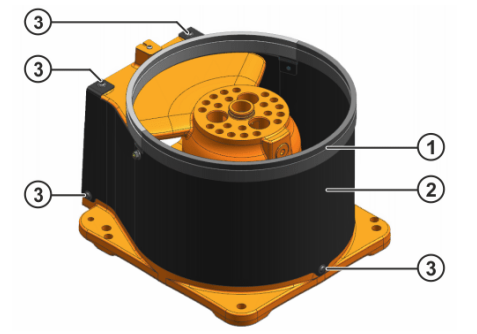
Figure: Cover on the base frame (example):
1 – Brush
2 – Cover
3 – M6x8-10.9 round head screw (5x)
Checking and greasing cable set A1
Procedure
- Carry out a visual inspection of the flexible tubes and clean If damage is detected, the cable set must be exchanged.
- Using a brush, grease the outside of the flexible tubes, the contact surfaces towards the base frame and the rear side of the
Wear protective gloves.
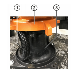
Figure: Cable set – base frame
1 – Cable set
2 – Rotating column
3 – Base frame
Mounting the cover on the base frame
Procedure
1. Push the brush onto the cover.
2. Place the cover with brush fitted around the base frame and align it.
3. Fasten the cover using 5 M6x8-10.9 round head screws.
Figure: Cover on the base frame (example):
1 – Brush
2 – Cover
3 – M6x8-10.9 round head screw (5x)
Concluding work
The following concluding work must be carried out:
• Remove grease residue.
• To spread the grease out evenly, move A1 of the robot.
Exchanging the toothed belt on A5
Description
The following sections describe the procedure for exchanging toothed belt A5 on a floor-mounted robot.
Equipment
The following equipment is required:
| Designation | Article number |
| Set of Allen keys 1.5; 2; 2.5; 3; 4; 5; 6; 8; 10 mm | – |
| Set of combination wrenches 6; 7; 8; 9; 10; 11; 12; 13; 14; 15; 17; 19 mm | – |
| Set of TORX key wrenches TX5; TX6; TX7; TX8; TX9; TX10; TX15 | – |
| Socket wrench set | – |
| Torque wrench min. 5 Nm to 50 Nm | – |
| Frequency meter TSM alpha 2 | 0071-053-386 |
Material
The following material is required:
| Designation | Article number | Quantity |
| Toothed belt 6 HTD-5M/325 HP | 0000-287-149 | 1 |
Procurement of spare parts
Defective components must only be replaced with original spare parts from KUKA Deutschland GmbH. Non-compliance nullifies warranty and liability claims.
A “Repair Card” is supplied with the exchange parts. This must be completed and returned to KUKA Deutschland GmbH together with the defective component in the following cases:
- Within the warranty period
- If, after consultation with KUKA Deutschland GmbH, an examination of the defective component by KUKA is required.
Tightening torques
The tightening torques can be found under: (>>> 12.1 “Tightening torques” Page 215)
These are valid for screws and nuts where no other specifications are given.
Screws of strength class 10.9 and higher as well as screws with test certification may only be tightened once with the rated tightening torque.
When the screws are first slackened they must be replaced with new ones.
Precondition
- The arm is in the horizontal
- The wrist axes are in their zero
- No tools are installed on axis
Work Safety
Warning
Danger to life and limb due to unintended robot motions
When carrying out the following work, the robot must be moved several times between the individual work steps. Unintentional movements of the robot can cause death, serious injury or material damage.
- While work is being carried out on the robot, it must always be se- cured by actuating the EMERGENCY STOP device.
- If work is carried out on an operational robot that is switched on, the robot must only be moved at reduced velocity. It must be possible to stop the robot at any time by actuating an EMERGENCY STOP de- vice. Operation must be limited to what is absolutely necessary.
- Warn all persons concerned before switching on and moving the ro-
CAUTION
Risk of burns from lubricants, components and surfaces Immediately after the robot has been shut down, lubricants, components and surfaces in the vicinity of the gear units and motors may have high temperatures. Touching them may result in burns.
- Wear protective
- Allow components to cool if
CAUTION
If the toothed belt tension is measured and adjusted immediately after the robot has stopped operating, surface temperatures are likely to be high and could result in burn injuries. Protective gloves must be worn.
Warning
Danger to life and limb due to live components
Components may remain energized after the robot system has been switched off. Death, severe injuries or damage to property may result.
- Switch off the robot system at the main switch and secure it to pre- vent unauthorized persons from switching it on again.
- Disconnect the power cable from the
- After switching off, wait at least 5 minutes and then check to ensure that the robot controller and power cable are deenergized.
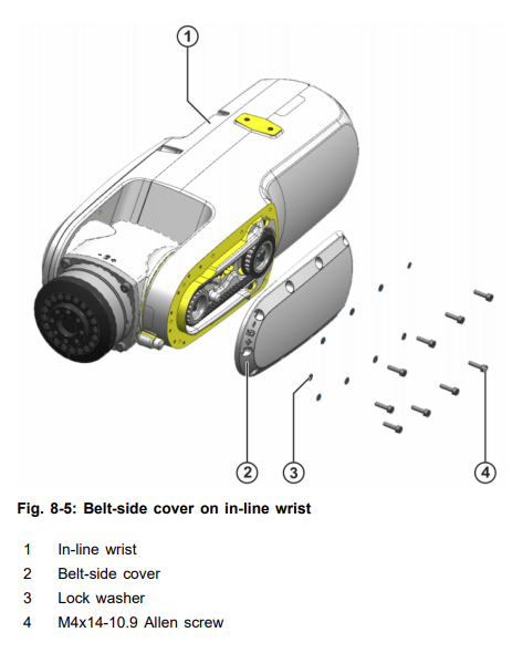
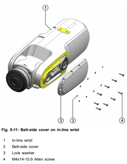
Removing the belt-side cover from the in-line wrist
Procedure
1. Unscrew 9 M4x14-10.9 Allen screws together with lock washers from
the cover.
2. Take the cover off the in-line wrist.
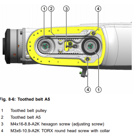
Removing toothed belt A5
Procedure
1. Remove M4x16-8.8-A2K hexagon screw (adjusting screw).
2. Remove 2 M3x6-10.9-A2K TORX round head screws with collar.
3. Slacken M4x16-8.8-A2K hexagon screw (adjusting screw) until toothed
belt A5 can be detached from the toothed belt pulleys.
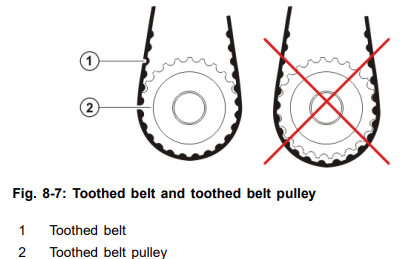
Installing toothed belt A5
Procedure
- Fit toothed belt A5 in the in-line wrist and place it on the toothed belt pulleys. Ensure that the toothed belt meshes properly with the toothed belt pulleys.
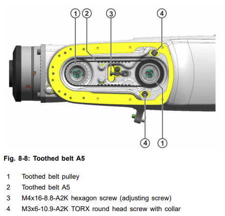
Adjusting toothed belt tension on A5
Procedure
1. Shift right-hand toothed belt pulley A5 to the right until the toothed belt is preloaded with roughly the right At the same time, tighten the 2 new M3x6-10.9-A2K TORX round head screws with collar until the right-hand toothed belt pulley A5 can no longer shift by itself.
above fig is 8-9
2. Put the robot into operation and move A5 two to three times by approx. 20° in the +/- direction before moving the axis into position to
measure the toothed belt tension.
3. Move A5 to the 0° position and secure the robot.
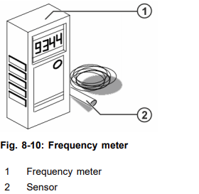
4. Put the frequency meter into operation. (>>> Fig. 8-10)
5. Pluck toothed belt A5 and hold the sensor at a distance of 2 to 3 mm
from the vibrating toothed belt. Read the measurement on the frequency meter.
Axis | Frequency |
5 | 180 ± 5 Hz |
6. If the frequency specified in the table is not reached, slacken or tight- en the M4x16-8.8-A2K hexagon screw (adjusting screw) slightly
(>>> Fig. 8-9).
7. Repeat steps 5 and 6 until the setpoint value has been
8. When the setpoint value is reached, tighten the 2 M3x6-10.9-A2K TORX round head screws with a torque wrench. Increase the tighten- ing torque to the specified value in several stages (>>> 8-9).
Installing the belt-side cover on the in-line wrist
Procedure
- Check the foam gasket on the inside of the cover for damage and ex- change if necessary.
- Place the cover on the in-line wrist and align
- Fasten the cover using 9 new M4x14-10.9 Allen screws together with lock washers.
Concluding work
The following concluding work must be carried out:
- Carry out mastering of A5.
- Run the program in T1 mode and look out for irregularities
Detailed information about mastering is contained in the operating and programming instructions for end users or system integrators.


