
Preface
Proper use and maintenance of equipment play an important role in ensuring normal operation, preventing equipment failures and accidents, extending service life, and maximizing economic efficiency. Equipment operators must undergo professional training and pass examinations before taking up their posts. During operation, they must strictly follow safety technical procedures and maintenance regulations. Unauthorized or improper operation is strictly prohibited.
Equipment maintenance should follow the principle of “prevention first,” eliminating potential faults at an early stage. The main tasks include preventing loose connections and abnormal wear, supervising operators to ensure proper equipment use as specified in operation procedures, preventing accidents, extending equipment life and overhaul intervals, ensuring safe operation, and maintaining equipment in optimal condition for production.
Adhering to the principle of combining use and maintenance, operators should achieve the “Three Goods”: good management, good use, and good maintenance; the “Four Skills”: knowing how to operate, maintain, inspect, and troubleshoot; and the “Five Fixeds” of lubrication: fixed personnel, fixed intervals, fixed quality, fixed quantity, and fixed points.
Operators of all types of equipment must perform regular and designated maintenance according to these regulations for the equipment they use, including robots, ground rails, cantilevers, gantries, welding machines, transmission systems, and other related tracks and devices.
Equipment Surface Dust Removal
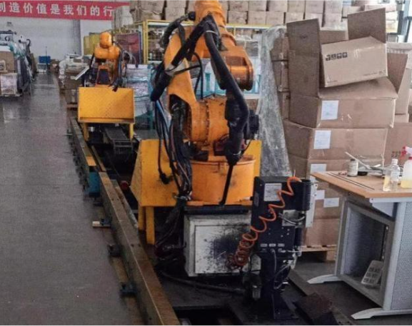
Robots, welding machines, electrical control cabinets, and other equipment accumulate large amounts of dust, oil stains, sludge, and other contaminants on their surfaces after long-term use due to workshop environmental conditions. These affect the appearance, operational accuracy, and proper functioning of the equipment, making regular cleaning necessary.
Handling Method: Wipe off sludge with a clean cloth. For thicker sludge deposits, use a steel scraper to remove them. Floating dust inside control cabinets can be removed with an air pump gun.
Maintenance Cycle: Wipe surface dust, oil stains, and sludge once a week with a clean cloth. Remove floating dust from enclosed spaces such as control cabinets with an air pump at least once a month.
Exhaust Fan Cleaning and Maintenance
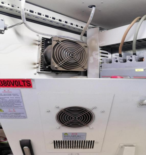
The exhaust cooling system is an important part of the equipment, including the exhaust systems of the welding machine, robot control cabinet, and auxiliary axis cabinet. Whether this system operates normally has a significant impact on the service life and performance of the equipment. Therefore, its maintenance is very important, ensuring that the exhaust fan runs properly and that the exhaust outlets are free of dust blockages.
Handling Method: Use a high-pressure air gun or similar tools to blow out the dust from the cooling mesh cover.
Maintenance Cycle: Depending on the site environment; under normal conditions, clean once a month.
Camera Cleaning and Maintenance
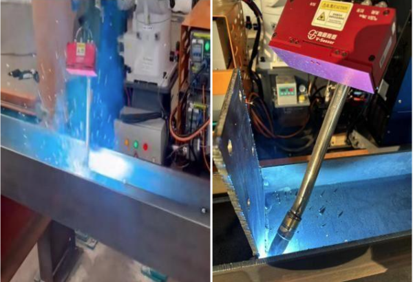
Cameras are precision mechanical components, requiring enhanced lens protection and proper heat dissipation. Lens blur directly impacts light acquisition and point cloud quality, which in turn affects camera positioning accuracy. Excessive camera temperature can affect performance and potentially damage core components.
Solution: Always close the camera cover when welding after scanning. Regularly inspect the protective glass and promptly replace any glass that is damaged or contaminated. Never operate the camera without the protective cover or glass installed. Also, regularly inspect the visual air pipe connector and replace any leaks immediately to prevent poor cooling due to insufficient air pressure and poor opening and closing of the protective cover, which can affect camera operation.
Maintenance cycle: Depends on the site environment and should be checked in a timely manner.
Teaching Pendant Use and Maintenance
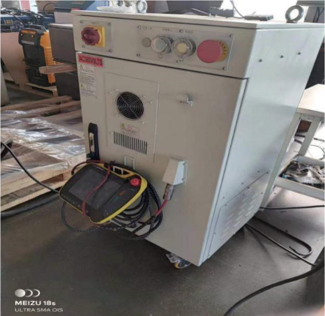
The robot teaching pendant is frequently used and is one of the main vulnerable components. Common faults include touchscreen damage, unresponsive touchscreen, cable damage or breakage, and loose cable connections.
Handling Method: Use the teaching pendant properly; pulling or yanking cables is strictly prohibited. The pendant must be used with a protective film, and the film should be checked regularly for damage and replaced promptly if damaged. When not in use, the teaching pendant must be placed on its designated hanger
Welding Machine Maintenance
WARNING! Electric shock can be fatal. Before opening the device
- Turn the main switch to the off position
- Disconnect the device from the grid
- Prevent reconnection
- Use suitable measuring instruments to ensure that live parts (e.g. capacitors) are discharged.
Brief description of the principle: The welding machine only requires very little maintenance and care under normal operating conditions, but in order to ensure its service life, the following maintenance methods must be followed.
– Welding Power Supply Maintenance
- The equipment identification nameplate must be riveted to the specified location on the casing; otherwise, internal components may be damaged.
- The connection between the welding cable plug and the output socket must be tight and reliable; otherwise, the plug and socket may burn out, causing instability during welding.
- Avoid short circuits between the welding cable and metal objects on the ground to prevent output short circuits.
- Avoid damage or breakage of welding cables and control cables.
- Prevent impact deformation, and do not place heavy objects on the welding power source.
- Ensure smooth ventilation.
- Regular inspection and maintenance are required.
Before maintenance, please do the following checks:
- Check whether the front panel status and welding specifications are displayed correctly, and whether the buttons and knobs are working properly.
- Check whether the line voltage of the three-phase power supply is within the range of 340V-420V and whether there is any phase missing.
- Check whether the input cable is connected correctly and reliably.
- Check whether the welding cable is connected correctly and has good contact.
- Is the gas line in good condition? Is the gas regulator or proportioner normal?
Note: The maximum voltage in the welding power supply is 600V. To ensure safety, it is strictly forbidden to open the casing at will. Safety precautions such as preventing electric shock should be taken during maintenance. The power should be turned off when installing welding cables or replacing welding gun accessories.
– Wire Feeding Mechanism Maintenance
- During use, avoid contact with water or other corrosive liquids. If accidental contact occurs, wipe immediately and keep the wire feeder clean at all times.
- After long periods of use, the wire feeding wheel and pressure wheel will experience wear. When the wear becomes severe enough to affect feeding stability, they should be replaced promptly.
- To ensure smooth wire feeding, regularly clean the wire feeding system to prevent increased resistance, which may affect feeding stability and welding quality.
– Water cooler maintenance
The coolant should be replaced every 12 months. Disposal of waste coolant must follow the requirements specified in the coolant usage instructions.
Coolant Draining Method:
1. First, drain the coolant from the water tank through the drain port.
2. Then, use an air compressor to blow air into both the inlet and outlet ports,discharging the coolant from the water pump and radiator into the water tank.
3.Finally, drain the coolant from the water tank again through the drain port.
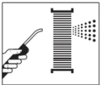
The radiator should be cleaned of dust every 6 months. If the welding torch or cutting torch overheats, it may be caused by excessive dust on the radiator, resulting in insufficient cooling capacity of the water cooler. In such cases, blow clean with dry compressed air, as shown in the figure.
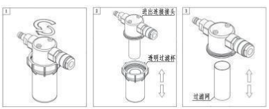
The filter should be cleaned once every 2 months. The filter is detachable, as shown in the figure. When a large amount of impurities has accumulated, it must be cleaned promptly. Remove the transparent filter cup/filter screen in the order shown (1–3), thoroughly clean it using compressed air or by running tap water at high flow, then reinstall it in the reverse order (3–1). Improper installation may create gaps and cause loss of filtering effectiveness.
(Warning! Be sure to clean thoroughly, and maintain cleanliness during the cleaning process to prevent secondary contamination.)
Notes:
- Please use coolant as specified to avoid damage to the radiator, water pump leakage, and motor failure.
- Do not start the water cooler without coolant or with insufficient coolant, as this may cause damage to the water pump or welding torch.
- Do not operate in environments containing silicon, acid, alkali, or salt components, as this may cause corrosion, leakage, and damage to the water cooler.
– Coolant Precautions
Ambient temperature>5℃, water can be used as coolant in the water tank
Warning: The water quality standard is deionized water or distilled water, which must meet the water quality standards. Otherwise, the scale produced may cause water seal leakage, rusting of the water pump, jamming and burning of the motor.
When the ambient temperature is ≤5℃, antifreeze must be used as the coolant in the water tank.
Warning: You must use an organic antifreeze. Otherwise, the corrosion inhibitors in inorganic antifreeze can cause water leaks in the water pump seal, welding torch overheating, or corrosion of the welding torch cable copper wire. It is recommended to use antifreeze that meets national standards and is used according to their requirements. Use antifreeze brands that clearly indicate “organic,” “OAT (Organic Acid Technology Antifreeze),” or “all-organic” in the name and ingredient list. Use antifreeze products that clearly indicate the absence of inorganic salts, such as “free of phosphates, borates, silicates, nitrates, nitrites, and amines.” It is strictly forbidden to use antifreeze products that clearly indicate “inorganic” in the name or that clearly indicate the presence of inorganic salts such as silicates in the ingredient list.
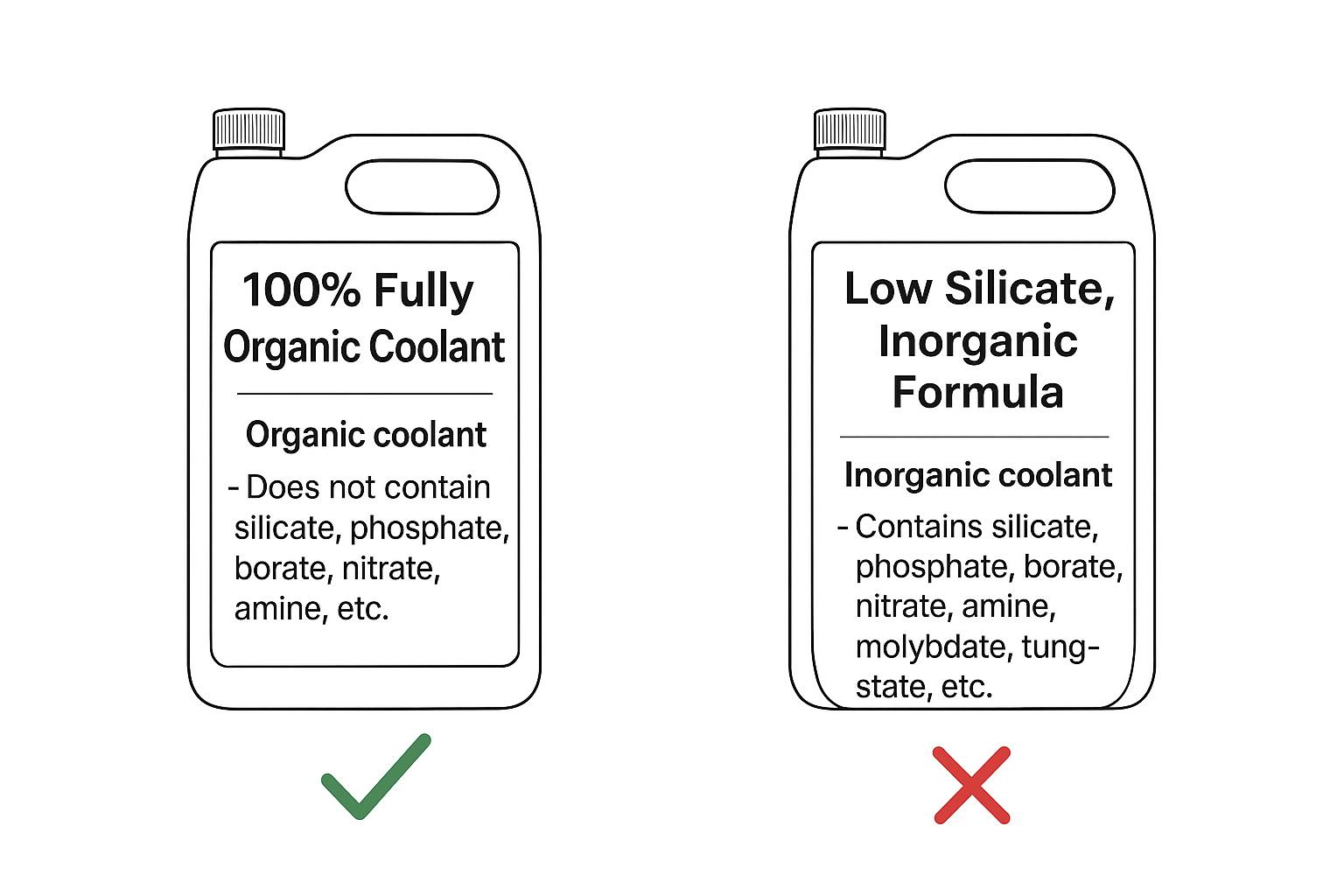
Functions of Organic Antifreeze: antifreeze, anti-corrosion, anti-boiling, and anti-scale.
The main indicator is the freezing point of the antifreeze.
When selecting antifreeze, its freezing point should be at least 10℃ lower than the lowest local temperature. For example: if the lowest local temperature is -15℃, choose antifreeze with a freezing point of -25℃ to ensure it does not freeze. Failure to use antifreeze as specified may result in the following consequences:
- In winter, the radiator inside the machine is easily cracked by freezing.
- Copper wires inside the welding torch cable may corrode and detach, entering the water pump and causing pump wear and leakage.
- Scale buildup may occur, leading to waterway blockage or water pump seizure.
Recommended Manufacturer: Langxun 100 Coolant
Model: Langxun 100 100% Organic Coolant
Freezing Point: -27℃
Applicable Regions: Areas with annual minimum temperatures higher than -17℃
Specification: 4kg
(Note! Do not mix different types of coolant. When replacing coolant, make sure to replace it completely.)
Welding Gun Maintenance
To ensure the service life and optimal performance of the welding torch equipment, routine inspection and maintenance of the welding torch system are required:
Daily Inspection:
- Check for any abnormalities in appearance.
- Before use, inspect the torch neck and integrated cable. If damaged, repair before use.
- If welding performance declines, carry out necessary cleaning and maintenance.
- Replace the contact tip promptly if the inner hole is deformed or arc ignition is difficult.
- In case of wire feeding issues, replace the contact tip and wire feeding tube.
- Replace worn parts with original welding materials in time.
Weekly Inspection:
- Check the installation status of the integrated cable to ensure it is not over-tightened or twisted.
- Clean and maintain the torch neck to prevent spatter from bridging the contact tip and nozzle, which could damage the welding torch.
Monthly Inspection:
- Remove the wire feeding tube inside the integrated cable and thoroughly clean it with compressed air.
- Check for wear on hoses.
- Inspect all connectors and screws for looseness, and check pipelines for damage.
Annual Inspection:
If necessary, repair and maintain electrical circuits.
Robot Oil Change and Maintenance
For robots, the lubricating oil must be replaced every 11,000 operating hours or every 3 years (whichever comes first). The required oil quantities for each axis, the orientation of each axis during oil filling, the steps for replacing the lubricating oil, and the procedure for releasing residual pressure in the chamber after refilling must all be carried out according to the instructions in this section. If you have any questions or require technical support, please contact our company’s after-sales service department in time.
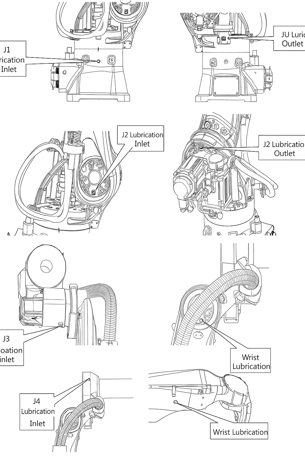
Below is the oil quantity table for lubricating oil replacement of the external ER series EFORT robots, along with schematic diagrams showing the oil inlet and outlet positions for each joint.
Table 4-6 Lubricating Oil Replacement Quantities
|
Supply Location |
Filling Quantity |
Lubricant Name |
Remarks |
|
J1 Reducer |
680 cc |
MOLYWHITERE No.00 – – – – – – – – |
Rapid oil injection will cause an increase in chamber pressure, leading to seal rupture. To avoid this, control the oil injection speed at ≤ 40 cc / 10 sec. |
|
J2 Reducer |
700 cc |
||
|
J3 Reducer |
310 cc |
||
|
J4 Reducer |
110 cc |
||
|
Wrist Component |
125 cc |
Position of oil filling and drain ports on each joint shaft
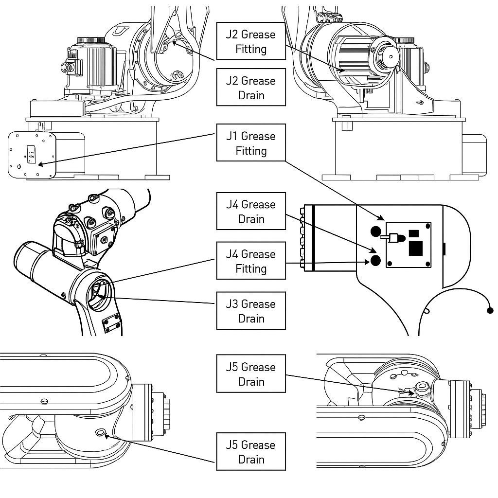
The following is a table showing the oil gauge for lubricating oil replacement and the locations of the oil filling and drain ports for each joint of the hollow wrist ARC series EFORT robots
| Table 4-6 Lubricant Oil Replacement Gauge | |||
| Provide Location | Amount of Refueling | Lubricating Oil Name | Remark |
| J1 axis reducer | 1310±10cc | MOLYWHITERE No.00 |
Rapid oiling will cause the pressure in the oil tank to rise, causing the sealing ring to crack and resulting in lubricating oil leakage. The oil supply speed should be controlled below 40cc/10 seconds. |
| J2 axis reducer | 870±10cc | ||
| J3 axis reducer | 370±10cc | ||
| J4 axis reducer | 480cc | BONNOC AX68 | Install quasi-dual time grease filling. |
Position of oil filling and drain ports on each joint shaft
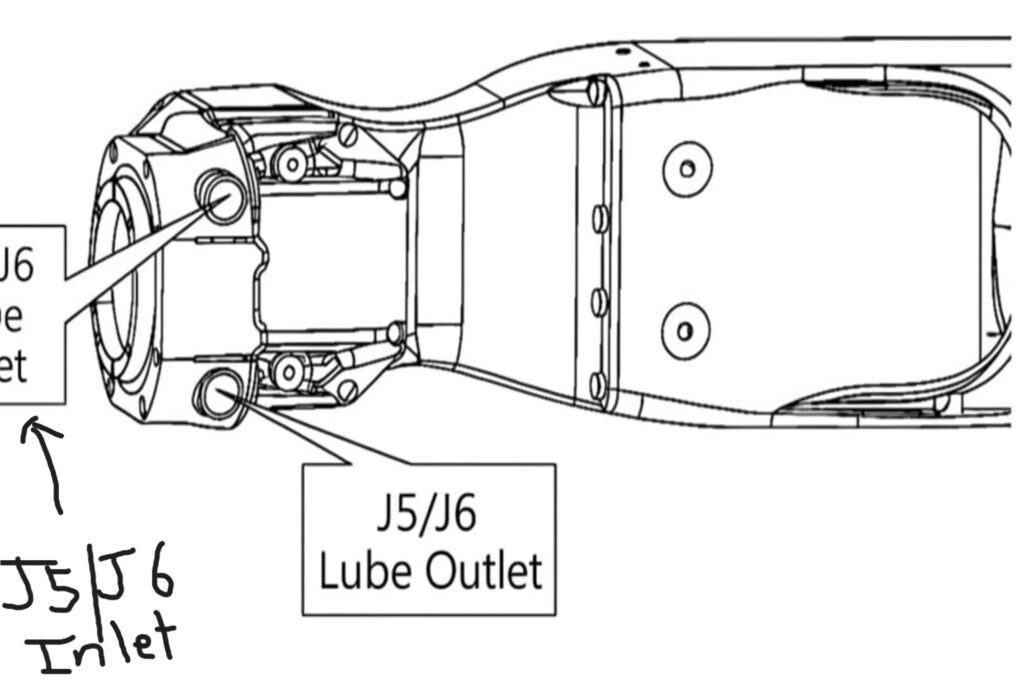
After refueling, operate the robot appropriately to release the residual pressure inside the lubrication chamber.
During this process, attach a collection bag under the lubrication oil inlet and outlet to prevent splashing of expelled oil.
To release the residual pressure:
- With the oil drain port open, move J1 axis within a ±30° range, J2/J3 axes within ±5°, and J4 and J6 axes within ±30°.
- Perform these motions repeatedly for at least 20 minutes at low speed.
If environmental conditions prevent the above movements, run the robot the same number of times; if the available axis angle is only half of the specified range, double the operation time.
After completing the motion, install the sealing plug on the oil drain port (use a combination washer or seal tape).
For detailed lubrication replacement procedures and operation guidance, refer to the “Robot Oil Change and Maintenance Operation Manual.”
Tightening of connecting bolts
The robot’s base and other components are primarily connected with high-strength bolts. Because the overall structure is dynamically loaded, these bolts inevitably loosen over time, affecting the equipment’s operating accuracy and creating safety hazards. The mounting brackets for the vision system and welding gun are also prone to loosening, causing deviations in visual accuracy.
Solution: Check whether the bolts are dropped or loose, and use an electric wrench or a manual torque wrench (with preset torque values) to tighten the bolts to the preset torque value.
The following is a table of recommended pre-tightening force settings for each bolt connection part of the workstation.
Recommended table for pre-tightening force of bolts for installing smart workstation equipment
| Serial number | Installation location | Bolt specifications | Pre-torque wrench specifications | Sleeve specifications | Pre-torque value |
| 1 | Welding gun (flange, anti-collision) installation | M4 | Small fly 1/4 1-6N.M | H3 (length 100mm) | 3.3N.M |
| 2 | Camera flange bracket installation | M6 | Dafei 1/2 (5-60N.M) | H5 | 8.5N.M |
| 3 | Camera box installation | M3 | Small fly 1/4 1-6N.M | H2.5 | 1.2N.M |
| 4 | Robot base installation | M14 | Dafei 1/2 (60-330N.M) | H12 | 200N.M |
| 5 | Robot base installation | M16 | Dafei 1/2 (60-330N.M) | H14 | 200N.M |
Maintenance cycle: Tighten all bolts thoroughly every three months of use.
Electrical System Maintenance (Distribution Box, Junction Box, etc.)
Workstations are equipped with numerous electrical devices, including electrical control cabinets, network cabinets, and distribution boxes. These devices require complex wiring. Prolonged use can lead to loose connections, exposed cables, and loose wires. These risks can easily cause short circuits and power outages, impacting normal equipment operation and posing safety risks. This area requires regular inspection and maintenance.
Solution: Check the switch wiring for loose cables and exposed wires. Check the neutral, live, and ground wires for proper connection, proper cable routing, and proper current and voltage. Any abnormalities should be addressed promptly. Always turn off the power and exercise caution when checking.
Maintenance cycle: Every 12 months of use, conduct a comprehensive inspection and overhaul of the distribution box, junction box, network cabinet wiring cables and power switches.