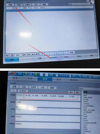
P1point
Press 3+ to raise the weapon, then press… 6+
If a deviation occurs after the gun rotates, adjust the tip of the welding wire so that it is as close to the tip as possible and demonstrate it.
P2point
Press 3+ to raise the weapon, then press… 6-
If a deviation occurs after the gun rotates, adjust the tip of the welding wire so that it is as close to the tip as possible. (Teaching)
P3point
Run the program at the source
Press 3+ to raise the weapon, then press… 5+Adjust the wrench to the angle of the welding torch. B is probably for-45degree
If a deviation occurs after the gun rotates, adjust the tip of the welding wire so that it is as close to the tip as possible. (Teaching)
P4point
Run the program at the source and teach.
P5point
Run the program at the source
According to 3+Wrench, welding torch moved upwards 200mmThe above is a demonstration.
P6point
Run the source program
according to 1-The key was that the welding torch moved backwards.200 mmThe above is a demonstration.
Run the source program
Calculate and save
Tool Verification
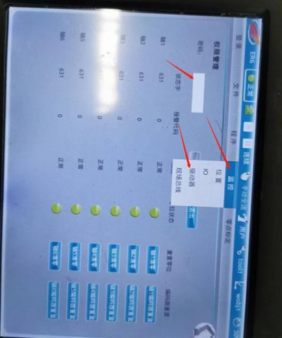
Source Position (if there is deviation, move the welding torch to align it with the calibration pin), switch the control panel to the monitoring position, and move it to -45 degrees by pressing 5 + angle B.
If there is any deviation, align the calibration needle.
Rotate angle A to 0 degrees using 4+ or 4-.
If there are any deviations, record the X, Y, and Z values of the current monitoring location.
Then move the teaching knob 1, 2, and 3 to align them with the calibration pin, adjust the tip of the welding wire so that it is infinitely close to the calibration pin, and record the X, Y, and Z values of the monitoring position after movement.
Calculate the difference between the value before and after the move, then divide that difference by 2 to get the value that needs to be changed.
Modify the coordinates in the tool’s coordinate system. (Calculate the difference in X and modify X in the tool’s coordinate system; calculate the difference in Y and modify Y in the tool’s coordinate system; modify the difference in Z in the tool’s coordinate system.)
After correction, rotate the welding torch 4+ or 4- 180 degrees and rotate the tip of the torch around the calibration needle (the error of about 1 mm after rotation is negligible).
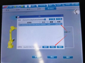
1. Import the calibration files to the control panel.
2. Open the file.
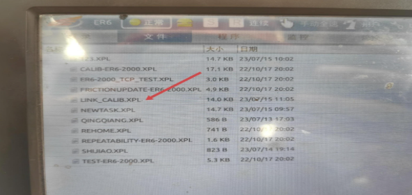
3. Click on the variable, select the name you want to register, and save it.
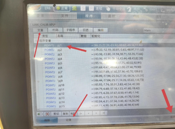
(60 points in total, divided into 3 groups, separated by approximately 1 meter from each other).
4. maintain.
5. Click the code to run the program. (The robot will not move during the process.)
6. Once the process is complete, you can check the logs.
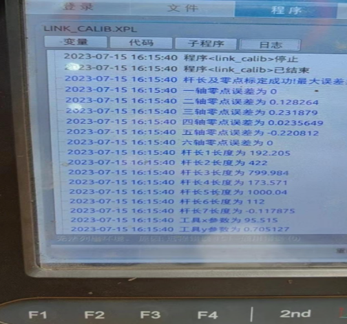
(The maximum error must be less than 0.7; otherwise, the cause needs to be investigated. The equipment should be restarted after the rod length is inserted.)
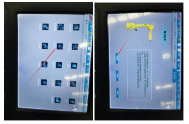
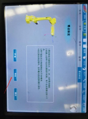
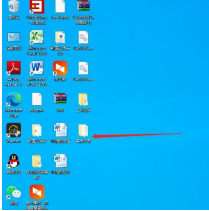
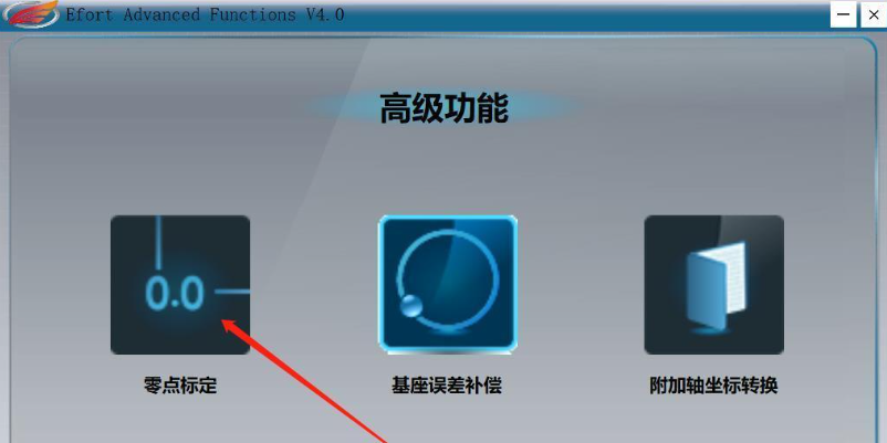
1. On the main interface of the controller, locate the zero-point calibration software and follow the steps in the image below to start the calibration.
2. The zero-point calibration is divided into 2 groups, each group with 10 points, adding up to a total of 20 points. As in tool calibration, the current positions from different positions are recorded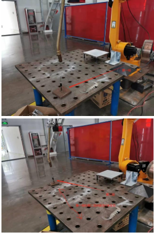
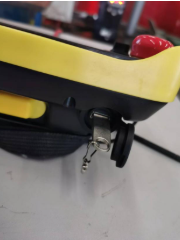
3. After calibration, use a USB stick of 32 GB or smaller to export the newly calibrated file.
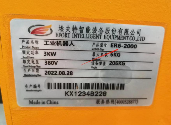
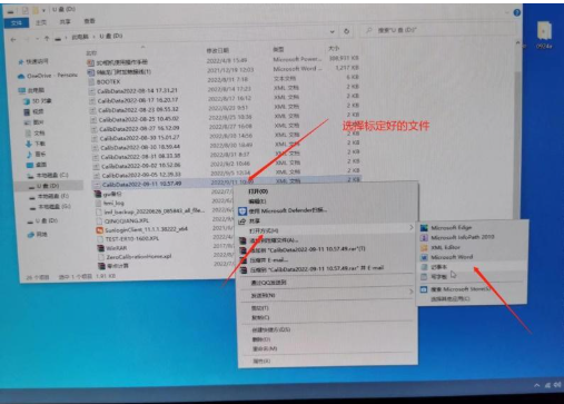
4. After exporting it from the driver, insert the USB stick into the computer, right-click on the file, select “Open With” and open it with Notepad. Then, write down the model of the robot; The model is located next to the base of the robot.
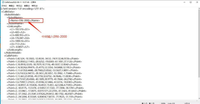
After entering and saving the information, you can proceed with the next operation.
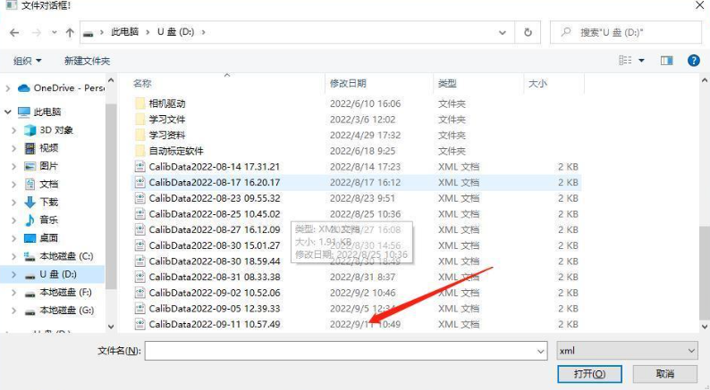
5. Open the zero-point calculation software and import the newly calibrated file. Pay attention and remember to record the time.

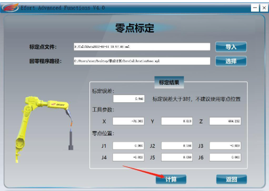
Once the calculation results are obtained, generate an articulation program on the controller and then enter the calculated values from axes one to six. Then, run this program.
After running the program, the robot will reach position zero.
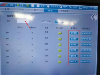
6. After the robot reaches the zero position, open the Monitoring — Servo Motor section on the controller, enter password 1975 to access, and reset axes 1 through 6. Note that zeroing axis 5 will result in a “Zero Point Loss Error”, which is unimportant; Simply close it, then zero the 6-axis, and the robot’s zero-point calibration is complete.
| Sub-section | Introducción del robot | Calibración TCP |
|---|---|---|
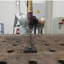
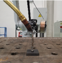
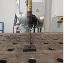
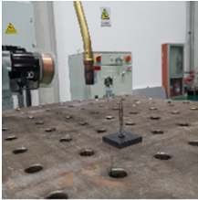
| Illustration | Diagram 1 of Vertical Welding Torch Displacement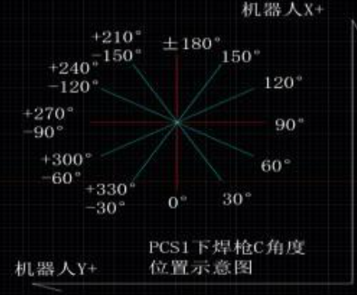 | Diagram 2 of Displacement of Vertical Welding Torch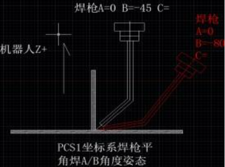 |
| Description | **Figure 1:** During robot welding under **PCS1**, the current value of the **C coordinate** is displayed; forward corresponds to the positive direction of the X-axis and to the left to the positive direction of the Y-axis. | **Figure 2:** During flat-angle welding, the posture of the **PCS1** coordinates is **A=0, B=-45**; during vertical-angle welding, it is **A=0, B=-70**. The value of C is determined by the position shown in Figure 1. The values of **A and B** are approximate and can be adjusted using the process package. |
| Illustration | 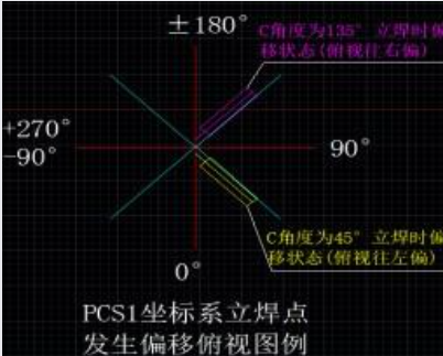 | 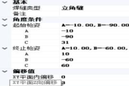 |
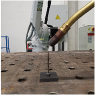
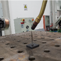
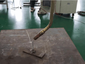
| Description | **Figure 3:** Example of torch position shift in **vertical welding**.
| **Modification path:** **Robot → workstation design → Tool Properties → Correction Rules**. Open the **compensation of offset values** and click **Add**, the top window appears. **Meaning of the parameters:** **Torch Starting Balance (Extend Position):** When the welding torch **PCS1** value is shifted within the boundaries of these two parameters, the torch applies a compensation value (offset in the **XY plane** and **Z direction**). **A(-10~10):** During normal welding, the angle A of the torch is 0; to avoid errors, it is set between **-10 and 10**. **B(-80~-60):** In the **vertical welding** position, the B angle of the torch is set between **-80 and -60**. |
| Sub-section | Introducción del robot | Calibración TCP | |||||||||||||||||||||||||||||||||||||||
|---|---|---|---|---|---|---|---|---|---|---|---|---|---|---|---|---|---|---|---|---|---|---|---|---|---|---|---|---|---|---|---|---|---|---|---|---|---|---|---|---|---|
| Diagram 1 of Vertical Welding Torch Displacement | Diagram 2 of Displacement of Vertical Welding Torch | ||||||||||||||||||||||||||||||||||||||||
| Illustration | 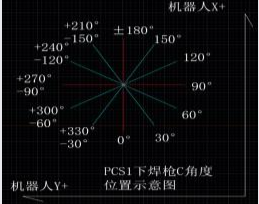 | 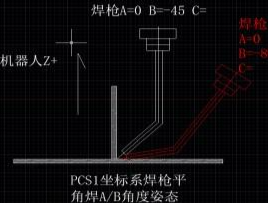 | |||||||||||||||||||||||||||||||||||||||
| Description | **Figure 1:** During robot welding under **PCS1**, the current value of the **C coordinate** is displayed; forward corresponds to the positive direction of the X-axis and to the left to the positive direction of the Y-axis. | **Figure 2:** During flat angle welding, the posture of the **PCS1** coordinates is **A=0, B=-45**; during vertical angle welding, it is **A=0, B=-70**. The value of C is determined by the position shown in Figure 1. The values of **A and B** are approximate and can be adjusted by the process package. | |||||||||||||||||||||||||||||||||||||||
| Illustration | 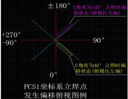 |
Figure 4 | |||||||||||||||||||||||||||||||||||||||
| Description | **Figure 3:** Example of torch position shift in vertical welding.
| **Modification path:** **Robot → workstation design → Tool Properties → Correction Rules**. Open the **compensation of offset values** and click **Add**, the top window will appear. **Meaning of the parameters:** **Torch Starting Balance (Extend Position):** When the welding torch PCS1 value is shifted within the boundaries of these two parameters, the torch applies a compensation value (offset in the **XY plane** and **Z direction**). **A(-10~10):** During normal welding, the angle A of the torch is 0; to avoid errors, it is set between **-10 and 10**. **B(-80~-60):** In the vertical welding position, the B angle of the torch is set between **-80 and -60**. | |||||||||||||||||||||||||||||||||||||||
| Illustration |
Figure 5 | B is usually around **-70**; therefore, it fits between **-90 and -60**. **C (limited to 30 degrees according to Figure 1):** In Figure 3, the yellow position of the torch has a displacement at the angle C = **45°**, so it is set between **31 and 60**; the pink position has a displacement at the angle C = **135°**, so it is set at between **121 and 150**. **Offset in the XY plane and Z direction:** used to compensate the torch to the correct position. In the top view, the offset to the right is considered a **positive value** (Figure 4), and to the left, a **negative value** (Figure 5). | |||||||||||||||||||||||||||||||||||||||


