Step 1
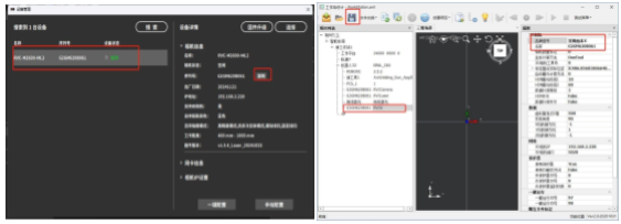
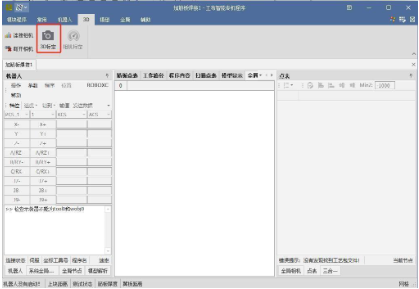
Open the main software, search for the **RuBen 3-in-1 camera**, and click to copy the camera’s serial number.
Open the software of the dedicated machine in the station design, select the **3D camera brand** as **Shenzhen RuBen X** and paste the copied serial number into the **name field**.
Step 2
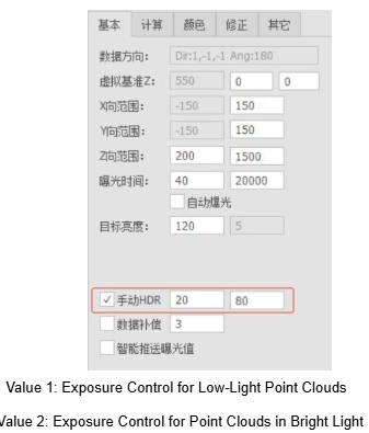
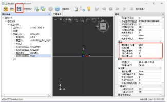
Make sure to adjust the virtual reference value Z according to the site conditions and the length of the gun, entering an appropriate data. Generally, it is recommended to use **550 or 600** (for a length of normal gun neck). The order of the addresses of the XYZ data is **-1, 1, -1**.
(Other camera brands should also adjust the direction order of the data according to the actual situation.)
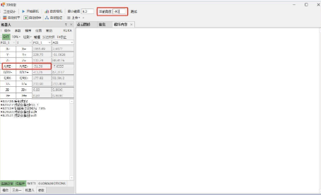
The **installation angle** should be checked and recorded according to the actual installation on site.
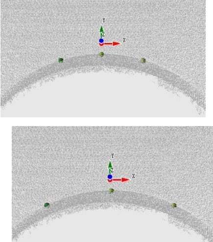
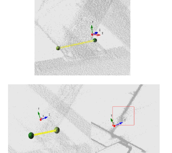
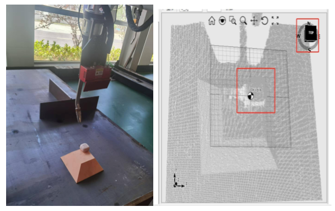
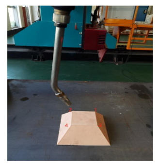
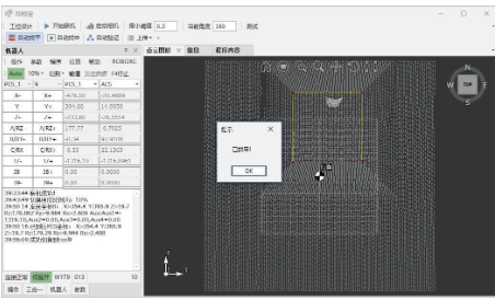
Note: To check the direction of the data and the installation angle, place a real reference object and compare whether the captured point cloud is in the same direction (as per the robot’s vision, as shown in the image below: if the object is placed in the upper right, the point cloud should also appear in the upper right).
After completing the filling, click the **Save** button to save the configuration changes, and then exit the workstation design page.
Step 3
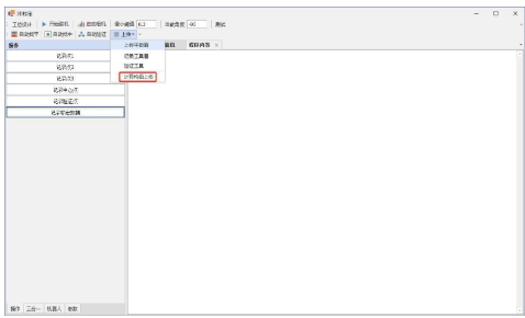
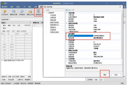
Click **Steel Profile Parameters** in the auxiliary list. In the composite view, set the camera brand according to the oscillating line camera model used, enter the camera’s serial number in the **camera name field**, and then click **OK**.
Step 4
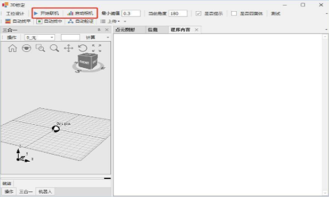
Click the **3D Calibration** button on the 3D page to enter the **3D Auto Calibration** page.
Step 5
Click successively on **Start Connection** and **Activate Camera** at the bottom of the page.
Step 6
Place the **calibration tetrahedron** directly below the robot camera. Note that the order of recording the points corresponds to the current view of the PCS: the **lower right point** is the **first point**, the **upper right point** is the **second point**, the **lower left** is the **third point**, and the **upper left** is the **fourth point**.
Step 7
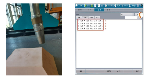
Use the teaching control to move the **TCP end** of the robot’s welding torch and perform the teaching point by point following the order of the points in the previous step. After the teaching is complete, save the data.
Note: Points must be recorded in the **tool1 coordinate system**. The length of the welding wire during registration should be the same as that used during calibration. When registering the four points, be careful not to change the robot’s angles **A, B, and C**.
Step 8
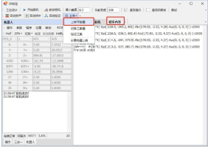
Click the **Upload Drawing Values** button from the drop-down menu. The program content will display the points recorded by the teaching control and will successively replace **Calibration Point 1**, **Calibration Point 2**, **Calibration Point 3** and the **Central Point**.
Step 9
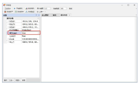
In the list of parameters, configure the option **Is it a tetrahedron?** to **true**.
Step 10
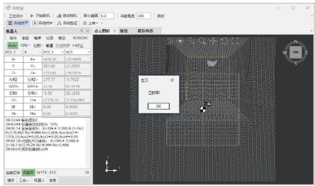
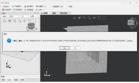
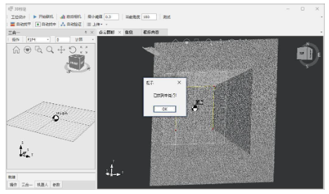
Move the camera up to directly over the calibration tetrahedron and click **Auto Leveling**. The camera will automatically perform the acquisition and calculation. When the calculation message appears, note if the calibration board calculation and the indicated rotation angle are normal; if so, click **Yes** until the **Leveling Completed** message appears.
Note: If the camera tool (**tool9**) does not contain values of calibration (e.g. on a newly installed robot or after updating the card files), copy the values from the **TCP tool (tool1)** to the corresponding camera tool number.
Step 11
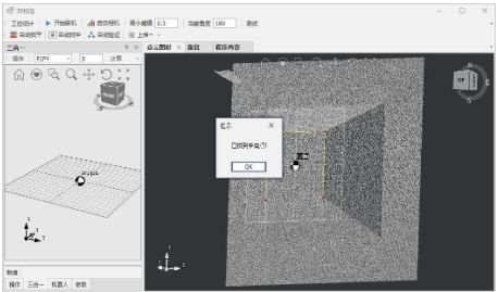
After completing the leveling, click the **Auto Centering** button. Similarly, note if the calculation of the **F1P4 calibration board** and the indicated motion offset are normal; if everything is correct, click **Yes** and repeat this operation until the **Centered Completed** message appears.
Step 12
After leveling and centering are complete, change the tool to **tool9**. Click the **Upload Tool Values** button in the upload list to upload the calculated tool values to the controller. With this, the calibration of the 3D camera is complete.
Step 13
If higher camera accuracy is required, perform a **multi-point tetrahedron calibration**. Based on the robot’s current **RZ angle**, record the corresponding angle (repeat the calibration four times with the values **90, -90, 180 and 0**).
Step 14
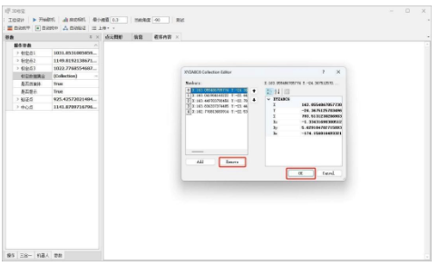
Click **Calibration Dataset** in the parameters section to check for data. If there are, click the **Remove** to delete all data and then click **OK**.
Step 15
After completing the fill, click **Auto Leveling**. The camera will automatically perform the acquisition and calculation. When the calculation message appears, note if the calibration board calculation and the indicated rotation angle are normal; if so, click **Yes** until the **Leveling Completed** message appears.
Step 16
After completing the leveling, click the **Auto Centering** button. Similarly, note if the **F1P4 calibration board** calculation and motion offset indicated are normal. If everything is correct, click **Yes** and repeat until the **Centered Completed** message appears.
Step 17
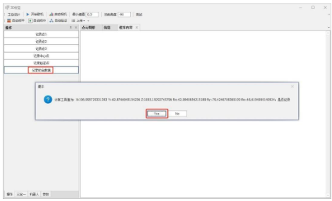
After leveling and centering are complete, verify that the tool number is **tool9**. Then, click **Record Calibration Data** in the Operations section to save the calibration data for this angle to the calibration dataset.
Step 18
Once all calibration data for all four angles is recorded, click **Calculate Average and Move Up** to load the data from Controller calibration. With this, the 3D calibration is complete.