Driver Application
- Login Password: 1975
- File: Location where the program is saved
- Program: Viewing and Writing Programs
- Monitoring: View position in spatial coordinates and I/O signals
- S: Turns green when the servo motor is turned on
- A: Running the control program in continuous or
step-by-step mode
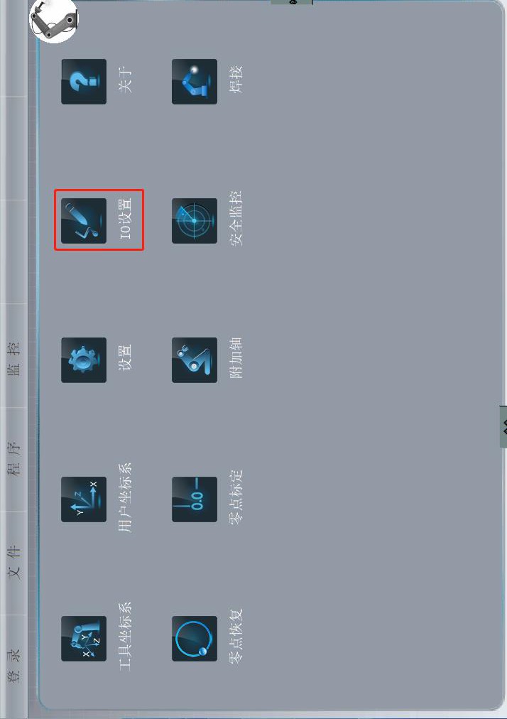
Controller Main Menu
- Tool coordinate system: used to calibrate the tool
- User coordinate system: used to calibrate the user
- Configuration: modify the robot’s IP and select applications
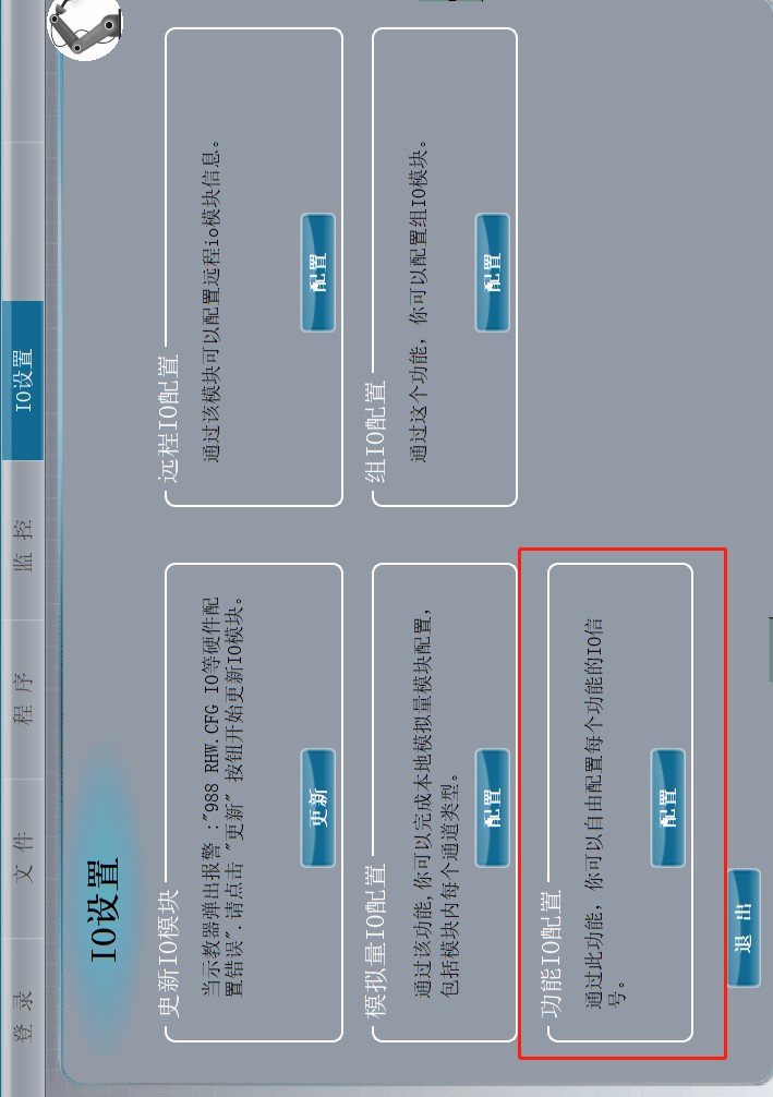
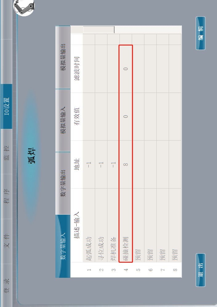
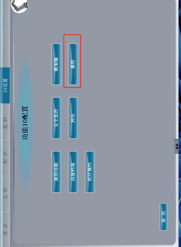
- I/O Configuration: I/O configuration and update
- Welding: setting welding parameters (loaded by file number)
- Equipment configuration: welding functions, no-load operation switch; Anti-collision mode must be activated
- Welding parameters: setting welding parameters (uploaded by file number)
- Oscillation parameters: setting oscillation parameters (loaded by file number)
- Welding protocol: select according to the brand of the welding machine (if communication is established with the welding machine, first turn on the welding machine and then the control cabinet)
- Vacuum operation: no arc, simulates the weld
path
- Collision detection switch: must be on
- Cartesian speed in idle operation: speed during idle operation
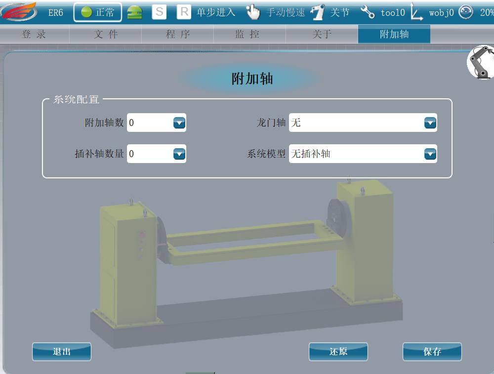 Additional axes
- Additional Axis Number, Interpolation Axis Number: Enter the value corresponding to the number of additional axes (the negative control of a double gantry robot cannot move the gantry crane, so it has one less additional axis than the negative control).
- Gantry Axis: Enter “None” if it is not a gantry; select “Move Away
Direction” if a gantry axis exists.
- System model: The earth’s trajectory is based on a linear interpolation on the X-axis. The gantry has higher priority the closer the additional axis is to the robot’s zero position.
- Additional axis settings: Direction: Enter 1 if the direction of movement of the additional axis matches that of the corresponding axis of the robot; otherwise, enter -1.
- Positive and negative limits: Range of motion of the additional axis.
- Reduction ratio: First, preset a reduction ratio of 100. Move the extra shaft (the greater the distance, the better). Note the distance that the corresponding additional axis is shifted at the monitoring position as M1. Measure the actual distance that the additional axis is shifted with a ruler such as M2. Formula: Actual Reduction Ratio = M1 * 100/M2
Controller Panel Description
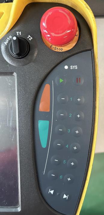 Auto: Remote Mode
T1: Selectable speed range: 1%~20% T2: Selectable speed range: 1%~100% ![]() Home button, right pause button Orange button: slow speed
Home button, right pause button Orange button: slow speed
Water Green Button: Step-by-Step Mode
1, 2, 3: movement along the X, Y, Z axes respectively 4, 5, 6: rotation around the Z, Y, X axes respectively F1: Shows errors
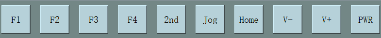
2nd: Switch to additional axles Jog: Change coordinate system Home: enter the main menu
- , V+: decrease/increase in speed by 1% PWR: On
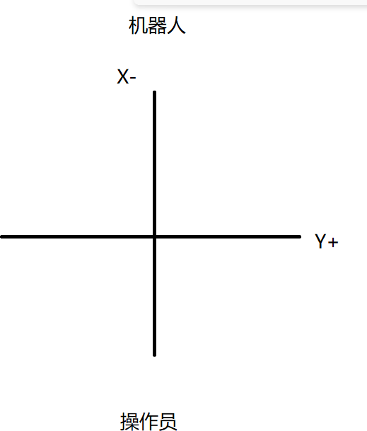
Machine coordinates
Programming Instructions
- MJointPJ: Articulation Instruction
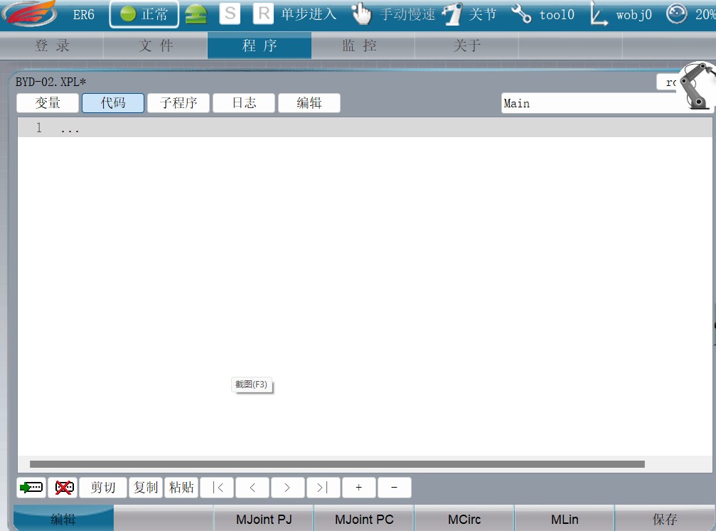
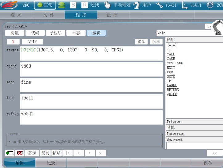
- MCirc: Arc InstructionMLin: Linear StatementTarget: Spatial Coordinate ValuesSpeedtool: tool usedRefsys: Work AddressCALL: Call an applet:= : assignment, used for input signals
- Data Direction: 1, -1, -1
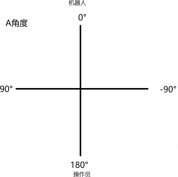
- Angle: depending on the installation direction, it can be 180° or 90°
- Range in X, Y, Z: image capture area
- Exposure time: the higher the light, the higher the exposure
- Threshold 1: 1 high point cloud density, 2
lower point cloud density; 2 is usually used
- Threshold 3: Complete based on the height of the scan points
- Three-sided threshold: used to calculate the bead in the groove
- Filtering Option: Usually 2 are used
- Face Removal Method: Recommended Origin for Better Calculation
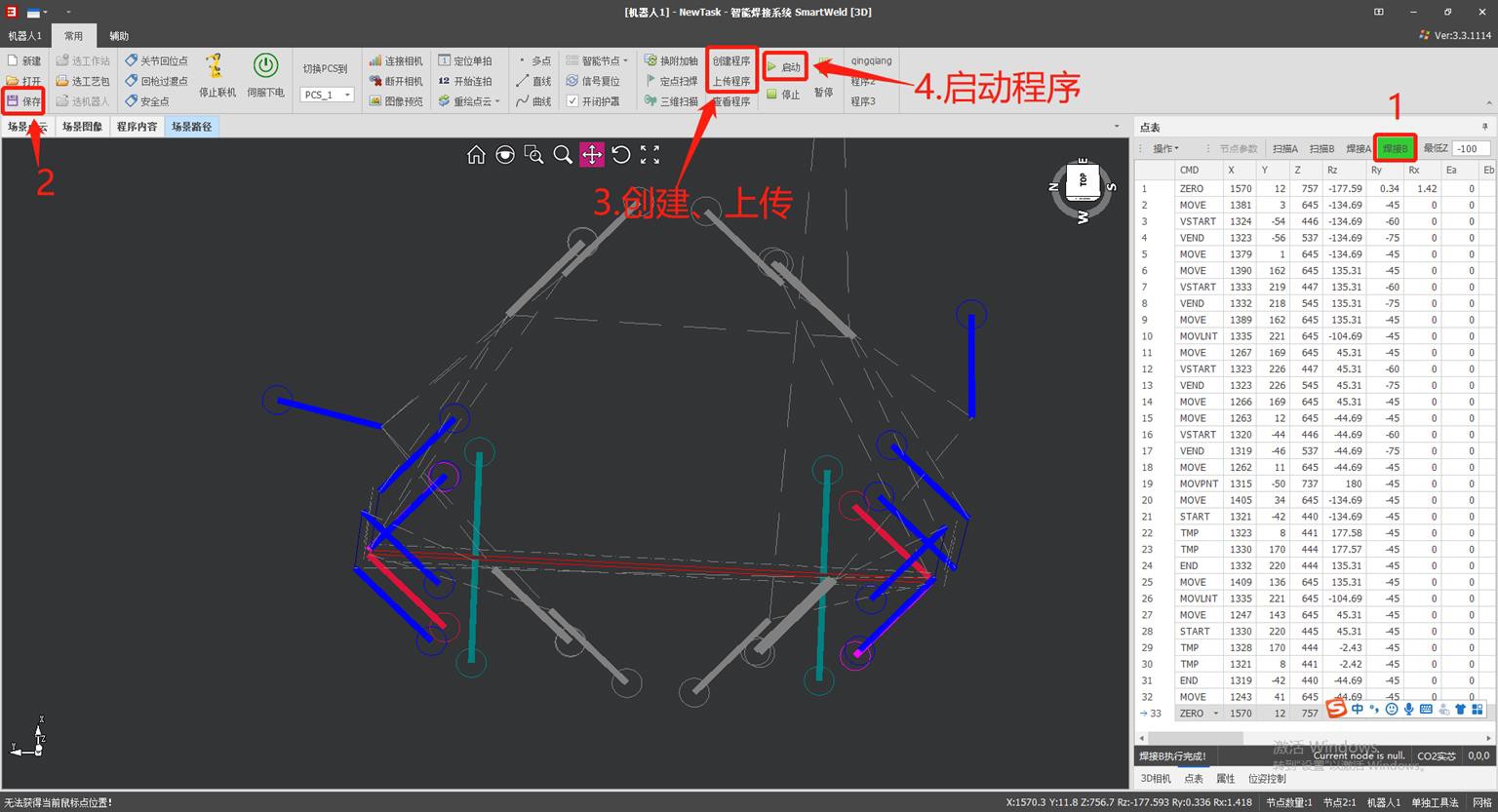
One-click start
- Function: Used for the same batch, reducing the steps of image capture and line marking.
- Installation: use a three-core cable; two are connected as signal lines to the input and written to the signal output at startup with a single click of the camera in the workstation layout, the other connects to 24VP.
- Use: taking images and marking lines on the first batch of components; downstream components are processed directly by weld scanning at fixed points (the deviation in the X and Y directions should not exceed 50 mm, and the angular deflection should be minimized, as the weld angle will not change).
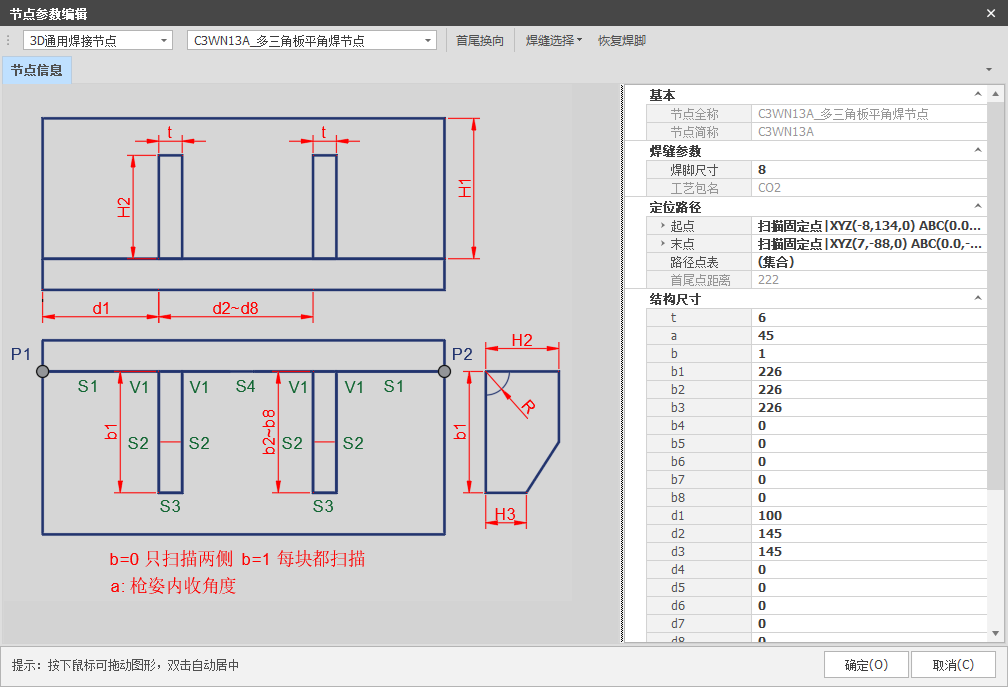
Introduction to 3D Common Nodes
Parameter Entry:
- Welding parameters: select the weld seam size and process package.Extra points: number of extra scan points (applicable for long cords).Structure Dimensions:T: Plate thicknessb: type of transition point, b=0 transition point as MOVLNT, b=1 as ZEROD1~D4: Corner Trimming DimensionsH~H4: Height dimensions (as shown in the figure)Seam selection: select the opening and closing of the bead, set special welding methods and welding dimensions.
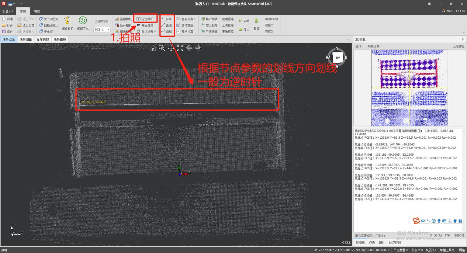
Directions for use:
- This node uses the line drawing method with two points, p1/p2 are the reference points to draw the line.If additional points are set, the midpoint (MID) will be added on the lanyard based on the number of additional points and the number of points selected.The height of the weld transition point is increased by 100 according to the value of H.
Precautions:
The value of b can only be 0 or 1.
- b=0: type of transition point MOVLNT, linear motion.b=1: type of transition point ZERO, articulation movement. b=1 is generally used to avoid collisions with the torch.
 Introduction to the most commonly used 3D nodes
17
Introduction to the most commonly used 3D nodes
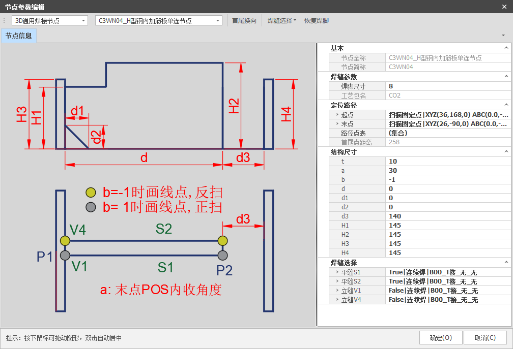
Parameter Entry:
Welding Parameters: Select weld seam size and process package.
Structural dimensions:
- t— Plate thickness
- b— Scan Control Direction
- d1~d2— Chamfer Size
- d3— Distance Between Wing Plate and Web Platea— POS endpoint retraction angle (default: 45°)
- H1~H4— Height dimensions (as shown in the figure)
Weld Seam Selection: Select to open or close the bead, set special welding methods, and define the weld dimensions.
Directions for use:
- This node uses thetwo-colon line tracing method; P1/P2are the guide points for the layout.
- The direction of the tracing is fixed: it starts on the vertically welded side of the wing plate and ends on the opposite side. The value of b determines whether the scan is forward
or reverse.
- When the value of d3 is less than 120, the value of a (scan retraction at the endpoint) is set to 45°; The value entered has no effect, usually a=10.
- Whendandd3have values, the length ofS1/S2is determined by the value ofd.Ifd=0andd3have value, the length ofS1/S2is calculated by subtractingd3from the scan result.Ifd=0andd3=0, the length ofS1/S2is based on the actual length of the scan.
Precautions:
- ThePOSplot start point is taken with theF3P2feature, while the end point depends on the value ofd3:Yesd3 > 120, The endpoint feature isF2P2.Yesd3 < 120, The endpoint feature isF3P2.
- Due to the particularity of the characteristics of the points, the starting point of the tracing must beon the side closest to the vertical weld, and the direction of the scan is controlled by the valueb.
17
Introduction to 3D Common Nodes
- Structural Dimensions: t—Plate Thickness
- a—Inward scan angle (default, 45° when the value of a is 0)
- a1—Increasing the inward angle for denser spot welding
- b—Control the direction of the weld
- d1/d2—Spot Correction Quantity, Weld Indentation Quantity, Corrected Wrapping Angle
- c1/c2—Welding leg coefficient (applicable to push welding)
- b1/b2—Wrapping Angle Length
- H1~H2—Height (as shown in the figure)
- Weld selection: Select the opening and closing of the weld, set special welding methods and weld dimensions.
- Directions for use:
- 1) This node uses a two-point drawing method; P1/P2 are drawing reference points.
- 2) The direction of welding is set according to the value of b. If denser points are configured, the number of intermediate MID points in the weld will increase based on the number of denser points and the number of denser point sampling points.
- 3) Value a (inward scanning angle): a value of 0 is equivalent to 45 degrees by default, usually a=10.
- 4) The sequence of start and end points of the S1/S3 welds is controlled by the value b.
- 5) B1/B2 refers to the length of the wrapping angle (the distance from the position of the gun to the end point of the S1/S3 weld where the position of the gun changes). When b1/b2 is 0, the default value is 20.
- 6) If a value is entered in d1/d2, the weld length will increase or decrease according to the weld length generated by scanning and sampling.
- 7) The value a1 refers to the increase in the inward welding angle (RZ value) of the densified points.
- Notes: 1) When the s2/s4 weld is selected as open, the value b has no effect.
- 2) The value of a1 (increase of the inward weld angle of the densified points) cannot be greater than
18 45.
Introduction to Common 3D Camera Nodes
- Introduction to Parameters: Welding Parameters: Select the size of
the welding leg and the process package.
- Structural dimensions: t—plate thickness
- D1~D4—Corner Size
- D5—S2/S4 Weld Depth
- D6/D8—Length (as shown in the figure)
- H1~H4—height (as shown in the figure)
- Weld Selection: Select the weld opening and closing, set the special welding methods and weld dimensions.
- Directions for use:
- 1) This node uses a two- or four-point drawing method. P1/P2/P3/P4
are reference points for drawing.
- 2) When d1/d2/d3/d4/d5 is greater than or equal to 5, the flat weld is interrupted; otherwise, the welding is continuous.
- Precautions:
19
- 1) The value of d6/d8 must be greater than 0.
- 2) If welding close to the torch, change the drawing direction.
Description of parameters:
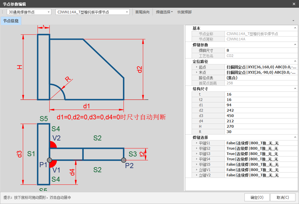 Welding parameters: select the bead size and process package. Structural dimensions:
T/T2 — Plate thickness
d1~d4 — length dimensions (as shown in the figure) R — Dimension of Angle Cut
H — height dimension (as shown in the figure)
Weld selection: select weld opening and closing, set special welding methods and necessary weld dimensions.
Directions for use:
1. This node uses the two-point line drawing method; P1/P2 are reference
points for drawing.
2. The drawing direction of this node is fixed: the start is the side with the winged plate in a vertical position and the end is the opposite side.
3. When d1/d2/d3/d4 = 0, the bead length is calculated based on the scan results; If D1/D2/D3/D4 are filled, the cord length will be calculated based on those values. If R is filled, the weld dimension will be calculated by subtracting the value of R.
Description of parameters:
 Welding parameters: select the bead size and process package. Structural dimensions:
t — plate thickness
B1~B2 — Weld Retraction Depth D1~D4 — Dimensions of Angle Cutting
D5~D6 — Length dimensions (as shown in the figure) H1~H2 — height dimensions (as shown in the figure)
Weld selection: select weld opening and closing, set special welding methods and necessary weld dimensions.
Directions for use:
1. This node uses the three-point line drawing method; P1/P2/P3 are reference points for drawing.
2. The angle between the three lines determines the actual angle of the component.
3. This node decides whether to add point-taking features based on the maximum bead length obtained from three surfaces, and adds point- taking features (F2P2) based on the length of the drawn line.
Introduction to Common 3D Camera Nodes
Description of parameters:
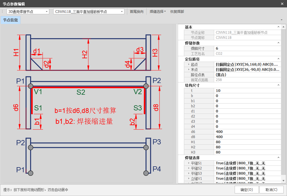 Welding parameters: select the bead size and process package. Structural dimensions:
t — plate thickness
b — if b = 1, it is calculated according to the dimensions d6/d8; if b = 0, it is calculated according
to the dimensions of the scan B1/B2 — Weld shrink depth
D1~D4 — Dimensions of Angle Cutting
H1~H3 — height dimensions (as shown in the figure)
Weld selection: select weld opening and closing, set special welding methods and necessary weld dimensions.
Directions for use:
1. This node uses two-point and four-point line drawing methods; P1/P2/P3/P4 are reference points for drawing.
2. If b = 1, it is calculated according to d6/d8; if b = 0, it is calculated according to the dimensions of the scan.
3. With the two-point line drawing method, you decide whether to add stitch-taking features based on the maximum bead length obtained from three surfaces and the value of d6/d8. With the four-point method, it is determined by the distance of the drawn line, and the aggregate point-taking characteristics are F2P2 (two points on two surfaces).
Caution: If the d6/d8 values are small, it is necessary to disable the retraction of the start and end points in flat welding and the transition distance from the gun base at the start and end points, to avoid collisions.
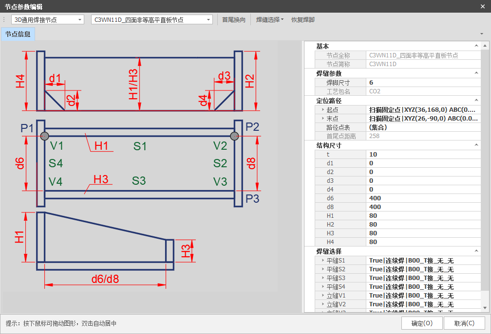
Description of parameters:
 Welding parameters: select the bead size and process
package.
Structural dimensions:
t — plate thickness
D1~D4 — Dimensions of Angle Cutting
H1~H4 — height dimensions (as shown in the figure)
Weld selection: select weld opening and closing, set special welding methods and necessary weld dimensions.
Directions for use:
1. This node uses the five-point line drawing method; P1/P2/P3/P4/P5 are reference points for drawing.
2. When d1/d2/d3/d4/d5 ≥ 5, the flat welding is interrupted; otherwise, continuous welding is performed.
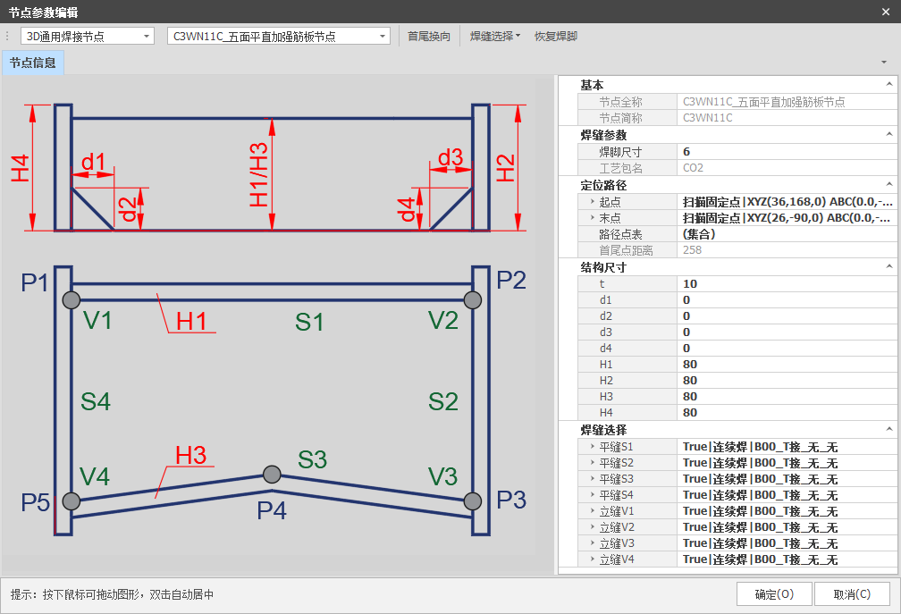
Description of parameters:
 Welding parameters: select the bead size and process package. Structural dimensions:
t — plate thickness
D1~D4 — Dimensions of Angle Cutting
D6/D8 — Length dimensions (as shown in the figure) H1~H4 — height dimensions (as shown in the figure)
Weld selection: select weld opening and closing, set special welding methods and necessary weld dimensions.
Directions for use:
1. This node uses the colon line drawing method; P1/P2 are reference points
for drawing.
2. The position of the line is fixed on the side with the largest dimension H.
3. The highest side is scanned and the positions of the flat and vertical weld on the other side are calculated using the values of d6/d8.
4. When the values of d1/d2/d3/d4 ≥ 5, if d1/d2/d3/d4/d5 ≥ 5, the flat weld is interrupted; otherwise, continuous welding is performed.
Caution: This node scans 2 POS points; The other side is calculated based on
the values of D6/D8, so these values need to be filled in accurately.
24
Introduction to Common 3D Camera Nodes
Description of parameters:
 Welding parameters: select the bead size and process package. Structural dimensions:
t — plate thickness
a — Internal retraction angle of the pistol position
R — Dimension of Angle Cut
b — if b = 0, only two sides are scanned; if b = 1, each piece is scanned B2~B8 — Length dimensions (as shown in the figure)
d2~d8 — length dimensions (as shown in the figure) H1~H3 — height dimensions (as shown in the figure)
Weld selection: select weld opening and closing, set special welding
methods and necessary weld dimensions.
Directions for use:
1. This node uses the colon line drawing method; P1/P2 are reference points for drawing.
2. When b = 0, only two sides are scanned (applicable to components with precise assembly); When B = 1, each part is scanned (applicable to components with assembly tolerances).
Caution: The internal retraction angle of the gun a should be between 0
25 and 90°, usually a = 45°.
Welding Process Package
26
| ParameterName | Subdivision ofparameters | Demonstration | Notes |
| Basic Info | Name (taking 8mm as an example) | 8mm fillet welding | The size of the weld seam and the type of shielding gas used |
| Observation | 8mm Fillet Welding – CO2 Gas Shielded Welding | Notes Information | |
| Weld size | Enter a numeric value | Welding Width | |
| Welding Orientation Type | Set selection | fillet welding, butt welding, or vertical welding, etc. | |
| Welding Parameters | Solder File Number | Call Archive | Enter the parameters in the corresponding solder file number on the control panel. |
| Welding speed | Enter a numeric value | Default 0(When a value is entered, the welding speed will be used; When set to 0, the speed corresponding to the solder file number on the control panel will be used.) | |
| Oscillation Parameters | Oscillating switch | T/F | Activate the rocking function? |
| Pendulum File Number | Call Archive | Enter the parameters in the corresponding arc file number. | |
| TransitionControl | BL transition length on outer corner | Enter a numeric value | The distance at which the welding gun posture is pre-adjusted when welding the outer corner. Default 2 |
| Inside Angle Transition Length BL | The distance at which the welding gun’s posture is pre-adjusted when welding inside corners. Default 22 | ||
| The starting point of the fillet weld is turned inwards. | T/F | Should the convergence function be enabled to the inside of the start and end point? | |
| The end of the fillet weld tapers inwards. | T/F | ||
| Inside angle of the starting point | Enter a numeric value | To prevent the welding torch from colliding, tilt the torch at an angle A.(Usually set to 35°) | |
| Parameter Name | Subdivision of parameters | Manifestation | Notes |
| Welding Torch Posture | Angle of the tip of the weapon A | Enter a numeric value | Welding GunPrescriptionAngle, default 0 |
| Flat angle welding B | Fillet Welding GunRyAngle (Default -45°) | ||
| B-angle correction | Exist “Flat Welding Angle B“ Add or Subtract According to | ||
| C Angle Correction | During welding, add or subtract to the base, usually resulting in ±10.(-10 is push welding, 10 is tensile welding) | ||
| Distance from the tip of the L1 weapon | When welding, the tip of the torch should be kept away from the welding line. Horizontal direction distance | ||
| Distance from the tip of the L2
weapon |
When welding, the tip of the torch should be kept away from the welding line.
Vertical direction distance |
||
| Control of vertical welding parameters | Distance from the tip of the L3 weapon | Enter a numeric value | When welding vertically, the distance between the tip of the torch and the weld bead…(Vertical welding at all angles) |
| Offset of the first vertical welding point | The position of the vertical welding starting point can be controlled. | ||
| Vertical Weld Endpoint Offset | The position of the end point of the vertical weld can be controlled.(Can be soldered a little further up to cover the corners) | ||
| Angle of the tip of the weapon B | Angle Ry at the start of vertical welding(Usually set to -65°) | ||
| B2 Gun Tip Angle | Angle Ry at the midpoint of the vertical weld(Usually set to -75°) |
27
Common Parameters
| Parameter Name | Subdivision of parameters | Demonstration | Notes |
| Interpolation Control | distance between start and end interpolation points | Enter a numeric value | When an inner bevel is required due to the size of the weld or the structure of the part, the distance between the end point of the inner bevel and the start and end points of the weld is called the start and end point interpolation distance (usually set to 50). Adjustments can be made in special cases. |
| Minimum interpolation seam length | Modify the settings based on the distance between the start and end interpolation points (default 100). | ||
| Distance between vertical welding midpoints | To prevent the welding torch from colliding with the workpiece, the initial angle when lowering it for vertical welding is not -90° (usually -65°). Once the torch is at a safe distance, the angle is adjusted to the optimal vertical welding angle of -90°. This position corresponds to the distance from the midpoint of the vertical welding point. | ||
| B-value of the wrapping angle at the end of the vertical weld | The position of the welding torch in the end corner (default -65°) can be modified as required. | ||
| Vertical Weld Endpoint Wrapping Angle 1 | T/F | Should the Corner Wrap Function of the Single-Sided Vertical Weld End be enabled? | |
| Wrapping Angle of Vertical Welding Endpoint 2 | Should the corner adjustment function be enabled for the vertical welding endpoint on the other side? | ||
| Vertical weld seam angle coefficient 1 | Relative Ratio Value | The ratio of the corner of a single-sided vertical weld to the thickness of the plate. | |
| Vertical weld seam angle coefficient 2 | The ratio of the thickness of the plate to the corner of the vertical weld on the other side (the sum of the two corner coefficients must be greater than 1). | ||
| ROBOX Program | Movement Speed | Enter a numeric value | Speed during linear motion commands (default v500) |
| Joint Movement Speed | Speed during articulated motion commands (default v25perc) | ||
| BL Transition Welding
Instructions |
BL Right Angle Welding with Rounded Transition (default 10) |
| Parameter Name | Subdivision of parameters | Manifestation | Notes |
| Weapon Posture Control | Movement distance to the right of the welding torch | Enter a numeric value | During the displacement of the welding torch towards the welding line, it is necessary to establish a transition point to meet the requirements of the torch posture. The distance to the right/forward corresponds to the X/Y coordinates of the torch at that point. |
| Welding Torch Feed Distance | |||
| Welding torch lower transition point height | During the movement of the welding torch towards the weld seam, it is necessary to establish a transition point that fits the required position of the torch The Z value corresponds to the height of that point. | ||
| transition point at the bottom of the welding torch start point | T/F | The transition points at the start and end of the weld must be determined based on the structure and dimensions of the workpiece to determine if they need to be adjusted and applied. | |
| Transition point on the bottom of the final spot welding torch |
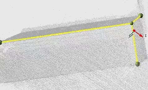
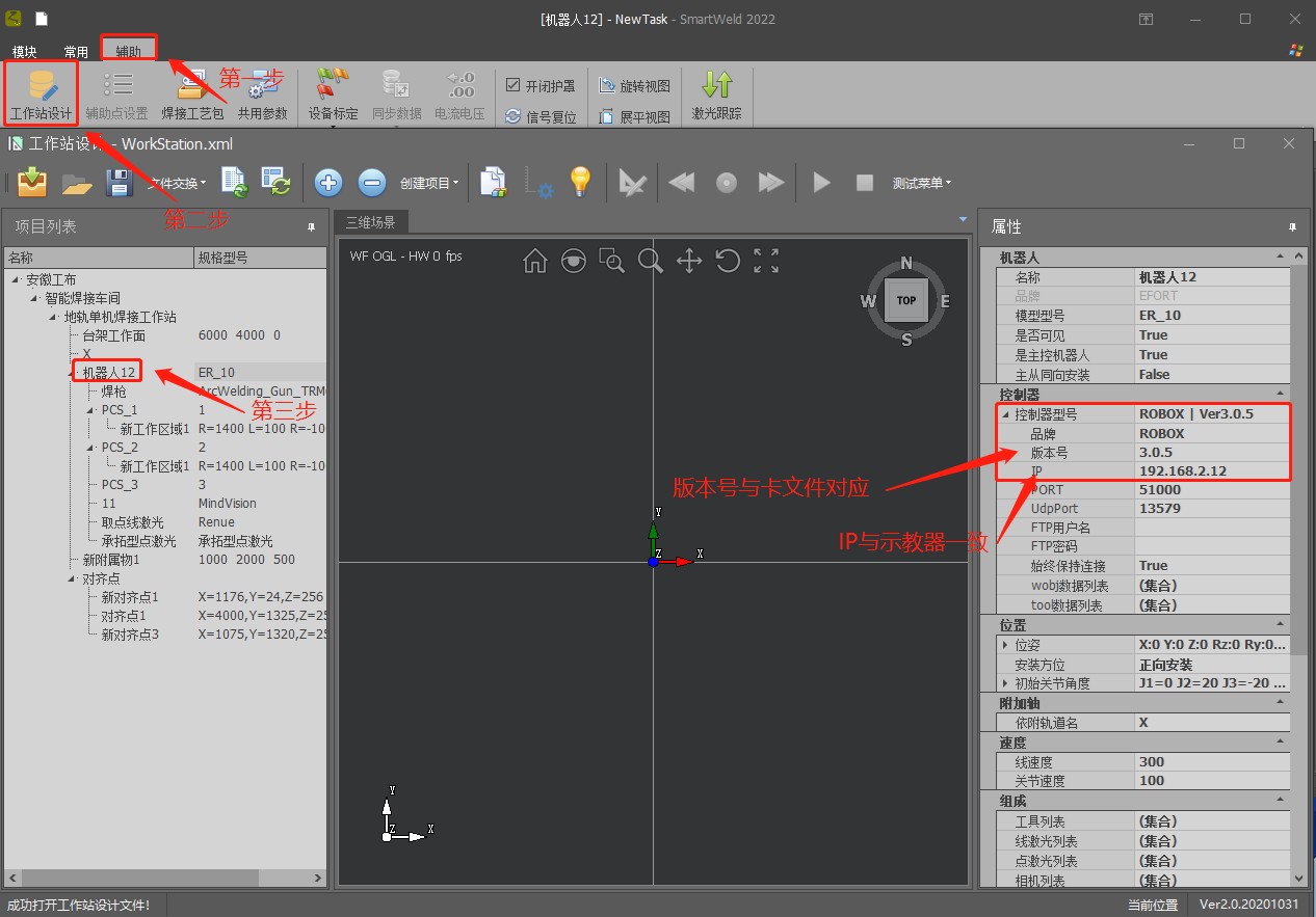
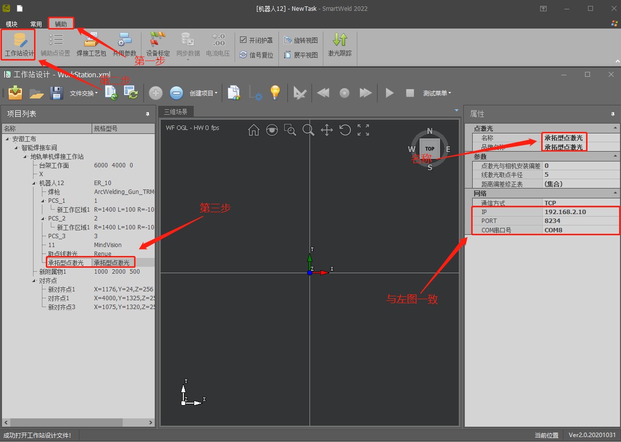
Workstation Design
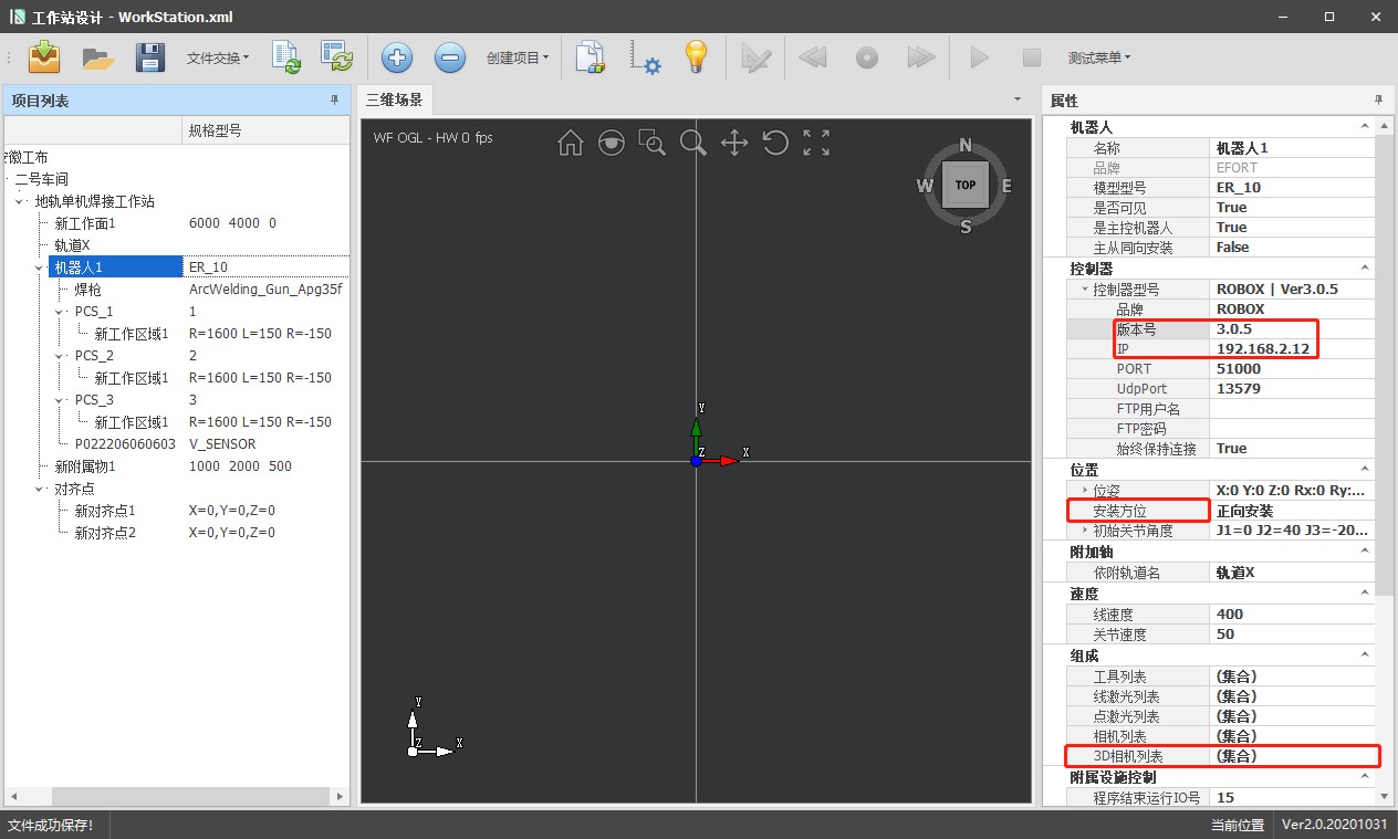
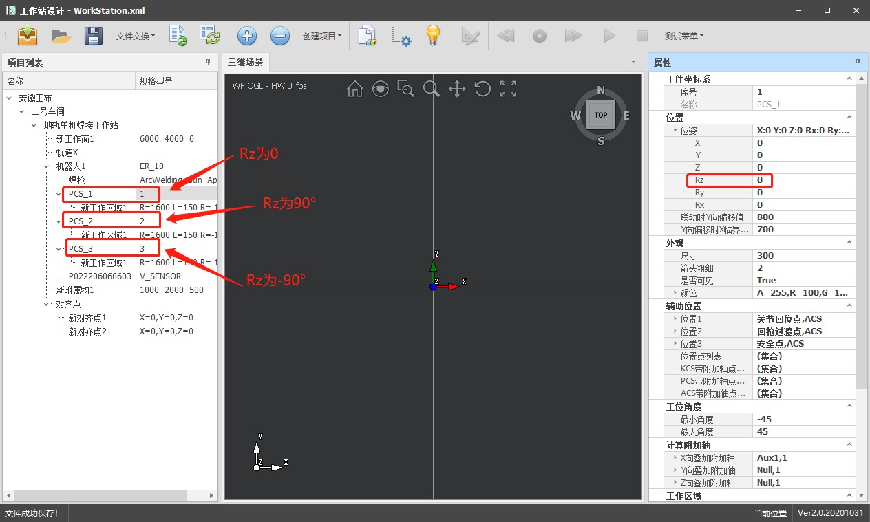
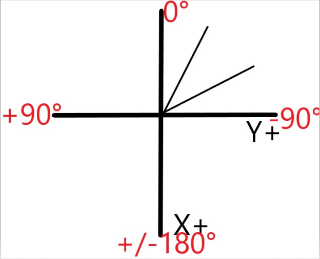
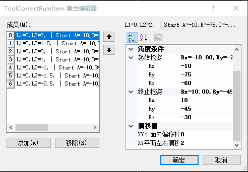 Rz: Angle of rotation around the Z axis Rx: Angle of rotation around the X-axis Ry: angle of rotation around the Y-axis
Conditional Angle: An angle range is defined that must include the weld angles to be modified; The minimum value corresponds to the initial stance of the pistol and the maximum value to the final stance.
XY plane offset compensation: distance between the wire tip and the weld seam in the forward/backward direction; positive value moves the tip away, negative value brings it closer.
Lateral displacement in the XY plane: lateral position of the wire tip with respect to the weld seam; negative values if the absolute angle goes from highest to lowest, and positive values if it goes from lowest to highest.
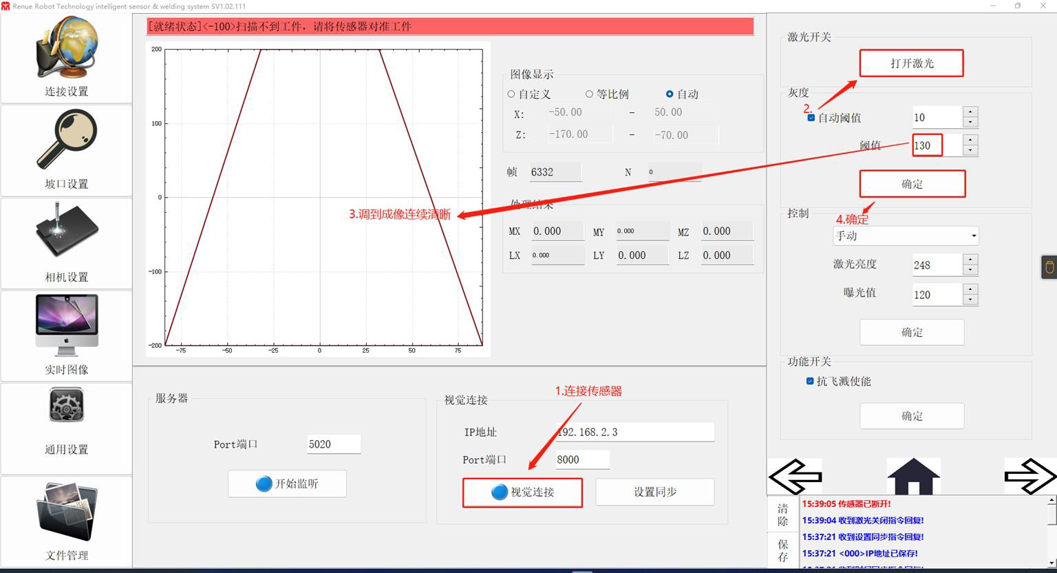
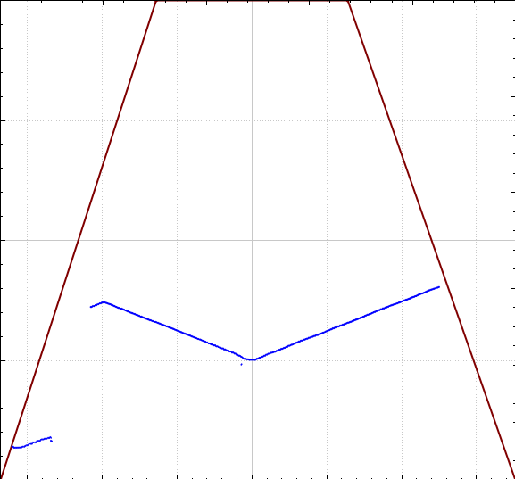
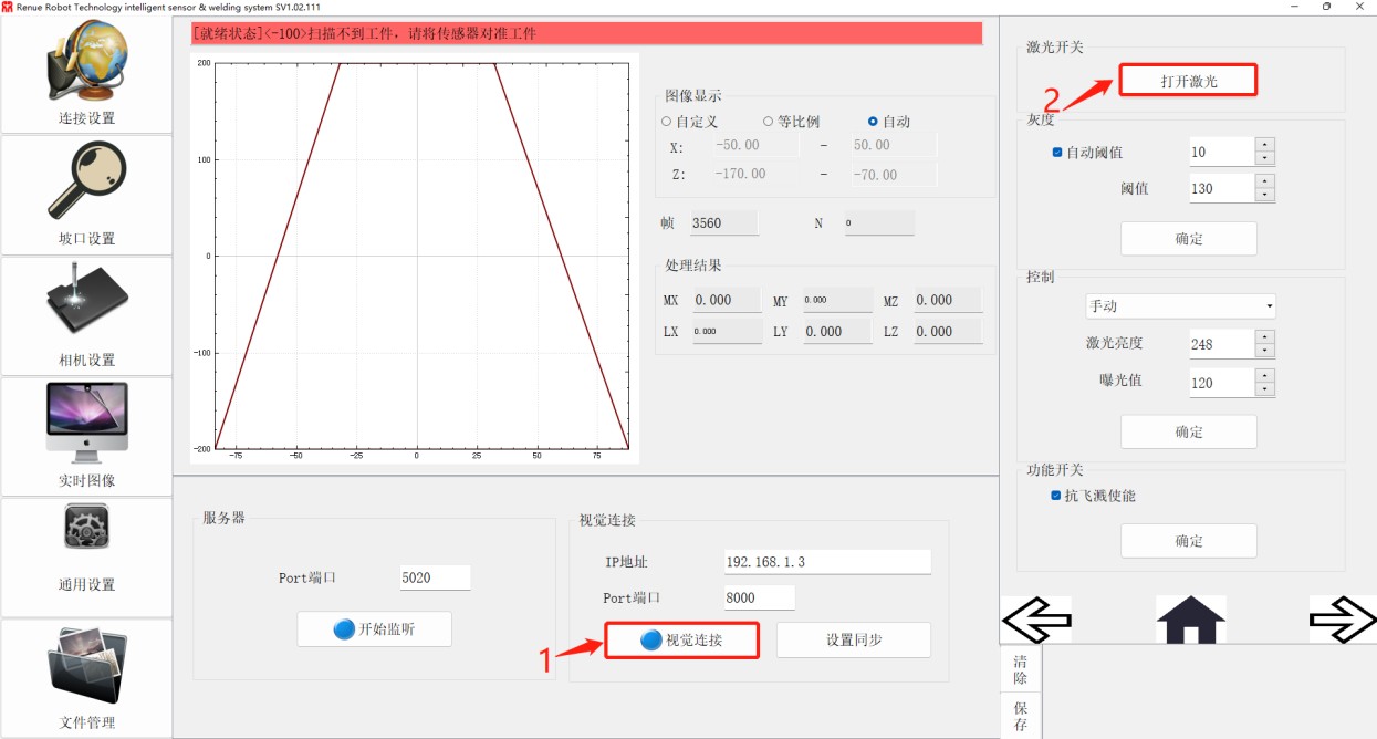
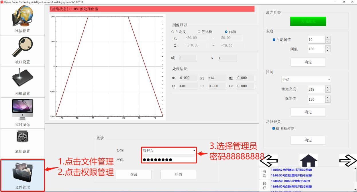
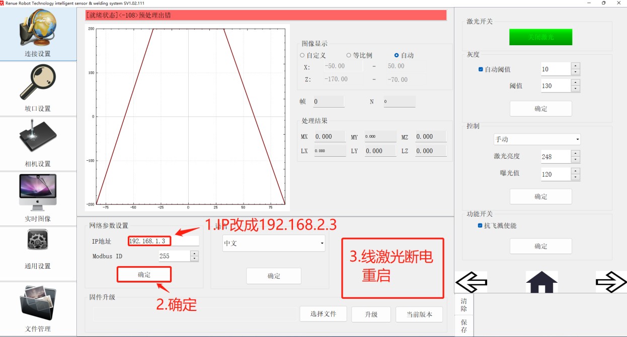
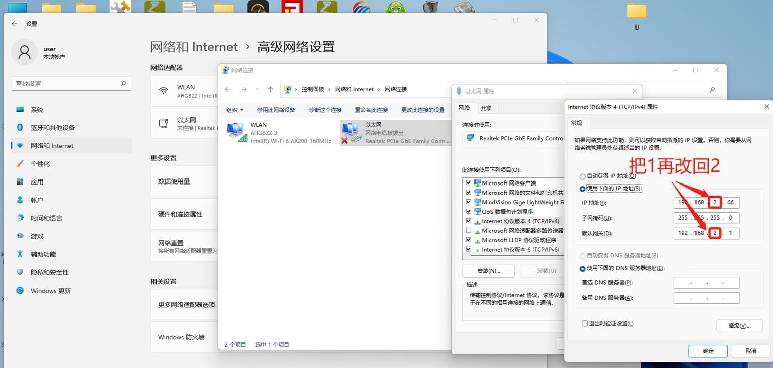
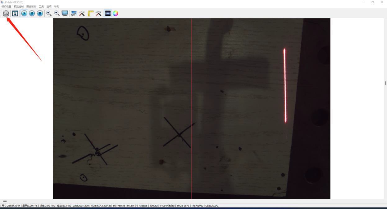
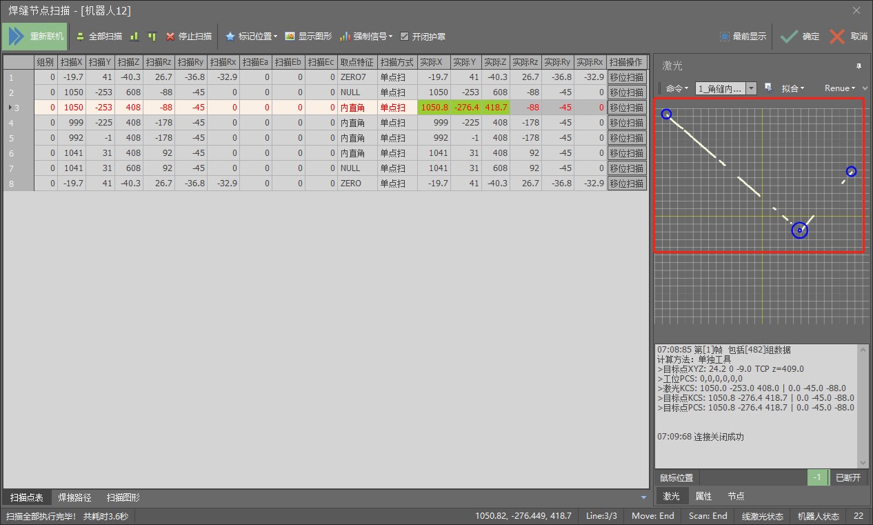 When the linear laser image is not continuous or the program has errors, it is necessary to adjust the threshold value in the Ruiniu software.
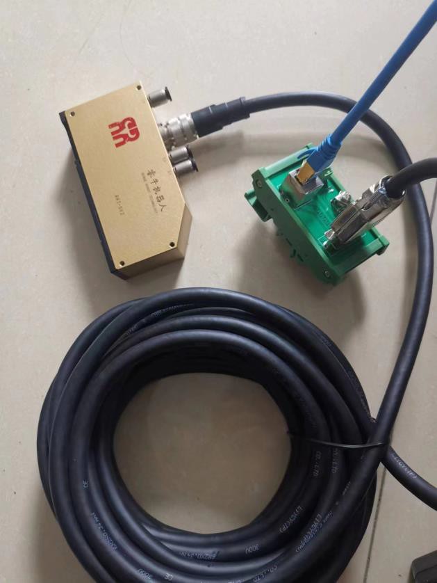
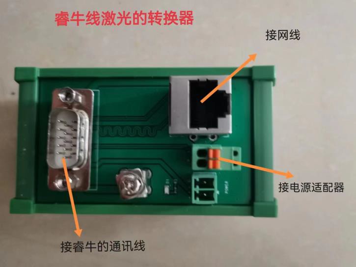
Linear Laser Adjustment
- t: Plate thickness
- a1: Distance from midpoint to vertical with flange tilted
- a2: Distance from highest point to vertical with flange tilted
- d1~d4: Through holes; Indicate the unwelded length
- d5, d7: Length of reinforcement from flange
- H1, H2: Flange height, measured from the top surface of the base plate
- H3~H8: Height of each part of the reinforcement; Indicate a uniform value if they are the same height
- V1~V4: Vertical welds, as shown in the red area of the figure on the left
- S1: Fillet welding between V1 and V2
- S2: Fillet Welding Between V3 and V4
- t: Plate thickness
- a: >0 Positive Scan (Scan Direction Matches Drawing Direction)
- b1, b2: Scan indentation at the start and end points
- d3, d4: Weld indentation at the start and end points
- c3, c4: Coefficient of thickness for push welds at both ends
- d1~d4: Dimensions on both sides of the reinforcement plate;
fill with 0 if the reinforcement plate is square
- H1, H2: Height of the reinforcement plate
- S3, S4: Short flat fillet welds on both sides of the reinforcement plate, equivalent to corner welds; extinguish the torch if these two welds are welded.
- Number of densified dots: Used when the weld is very long;
You can increase the number of scan points.
- Dimensions of Welding Leg: Complete as required; It can be found in the welding process package.
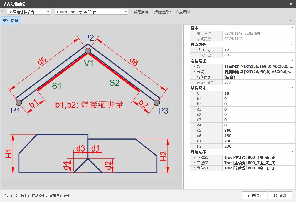
- t: Plate thickness
- d1, d2: Chamfer Dimensions
- d5, d7: Distance from vertical when the left and right side plates are tilted
- d6, d8: Length of left and right side plates
- H1, H2: Height of the left and right side plates
- H3, H4: Front and rear side plate height
- Other dimensions can be left blank
- S1~S2: Flat Weld
- V1~V2: Vertical Welding
- Dimensions of Welding Leg: Complete as required; It can be found in the welding process package.
- b: Length of the bottom edge of the elbow plate
- d1: Distance between the end of the first elbow plate and the bottom plate
- d2~d8: Distance from the left side of the current elbow plate to the left side of the previous elbow plate
- H: Height of the flanges at the left and right ends; set to 0 if none
is specified
- H1: Height of the reinforcement plate
- H3: Height of the highest point of the elbow plate
- H4: Height of the lowest point of the elbow plate; Can be set to 0 to disable corner covering when using a corner covering torch
- S1, S2: Flat Weld
- V1, V2: Vertical Welding
- Weld Seam Size: Complete as required, can be inquired in the welding process package.
- T: Plate thickness
- B: Horizontal length as shown in the figure left
- B1, B2: Length of the straight edges on both
sides according to the figure
- D1, D2: Arc Radius
- H: vertical length as shown in the figure left
- Weld Seam Size: Complete as required, can be inquired in the welding process package.
- T: Plate thickness
- B: Length measured as shown in the figure
- D: Measured length as shown in the figure
- H: Length measured as shown in the figure
- R: Arc radius
- Weld Seam Size: Complete as required, can be inquired in the welding process package.
- T: Plate thickness
- B1: Left Side Straight Plate Length
- B2: Right Side Straight Plate Length
- D1: Arc radius
- H: Length of the center plate
- Weld Seam Size: Complete as required, can be inquired in the welding process package.
- T: Plate thickness
- b: fill 1 if W > b1 and W > b2; fill 2 if b1 > W or b2 > W
- B1, B2: Length of left and right side plates
- D1, D2: Reinforcement Bevel Dimensions
- H1, H2: Height of the left and right side plates
- H3, H4: Reinforcement height
- W: Reinforcement Length
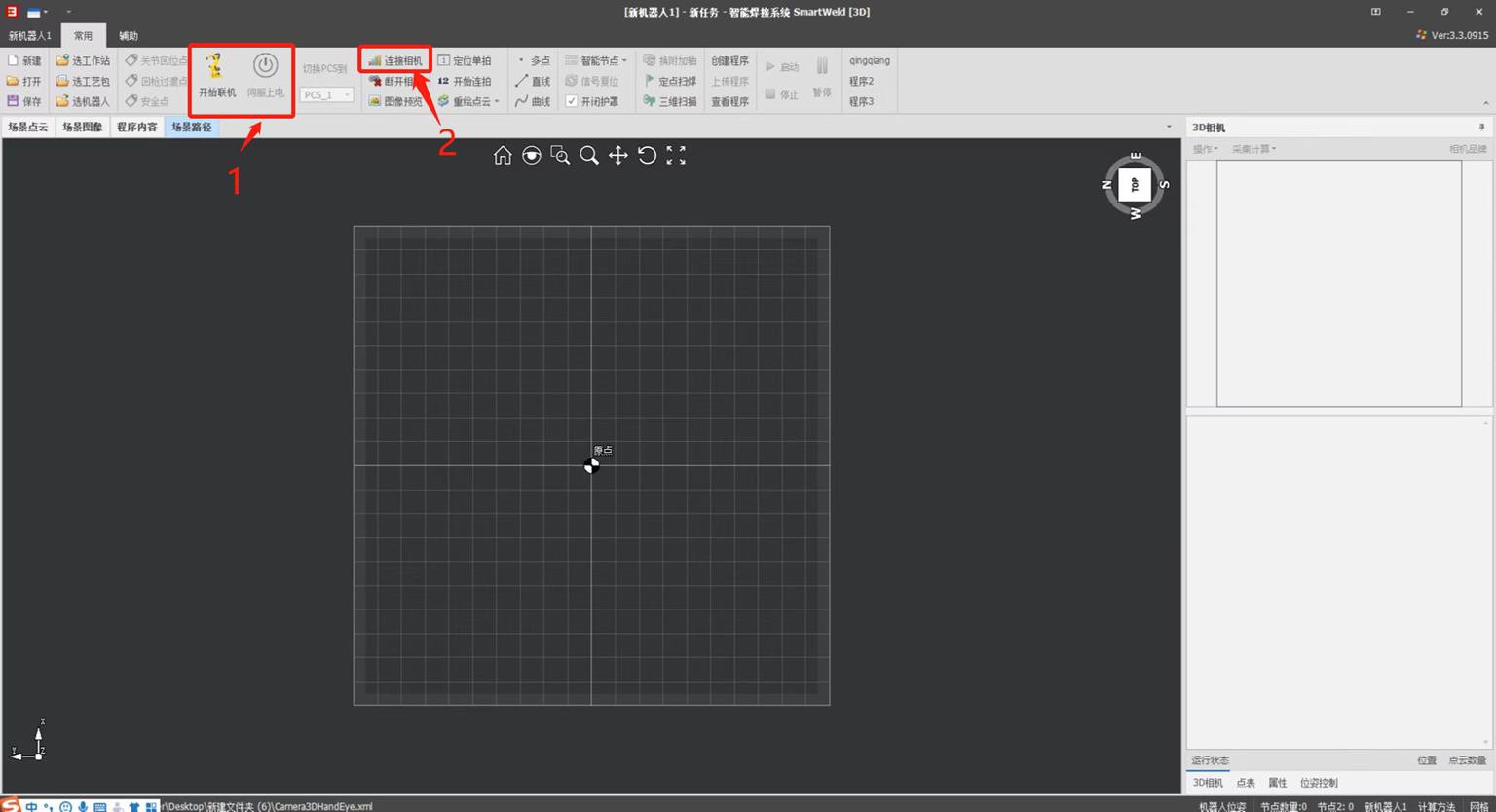
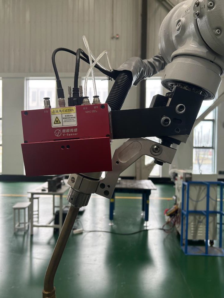
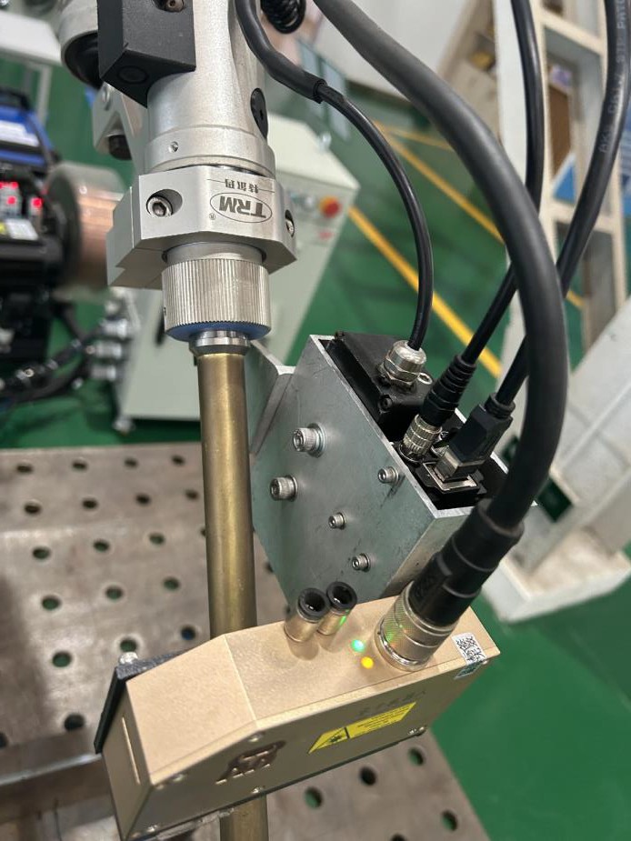
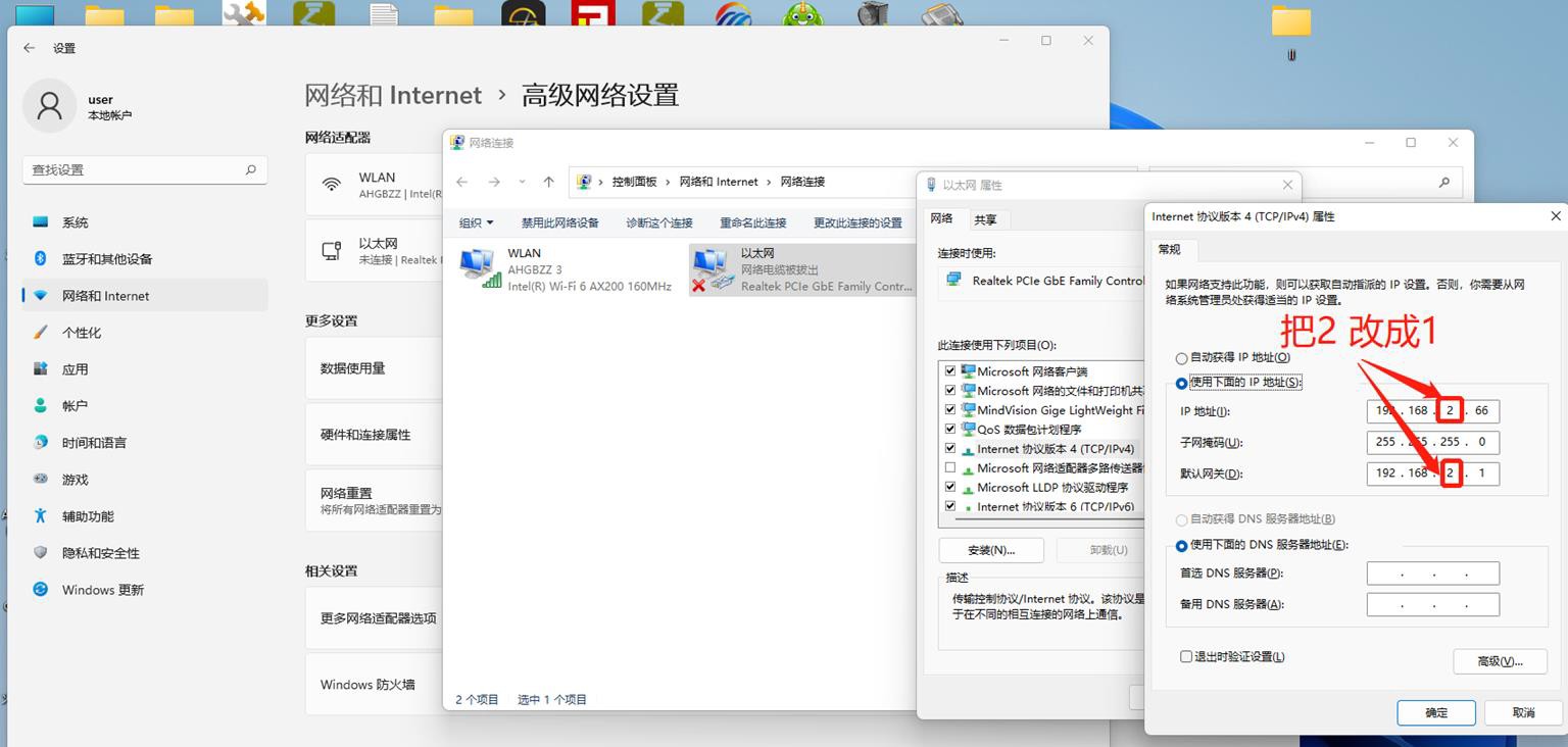
Installing the 3D Vision System
Connecting the 3D Camera Protector
- Each end of the solenoid valve has a wire connected to the output signal, and the other two wires are connected to 24sV DC G.
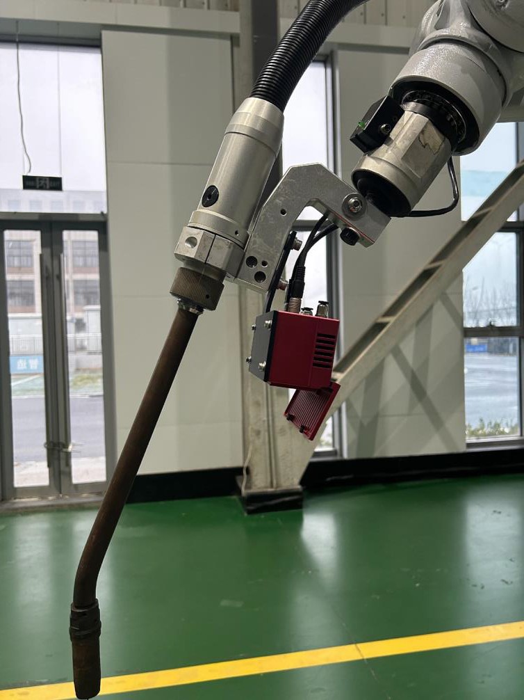
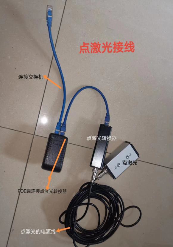
Installation of the linear laser vision system
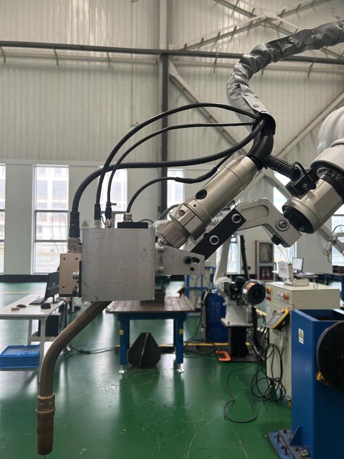
Installation of the linear laser vision system
Collision avoidance settings
Connect the black wire to the input and the brown wire to 24V DC.
53
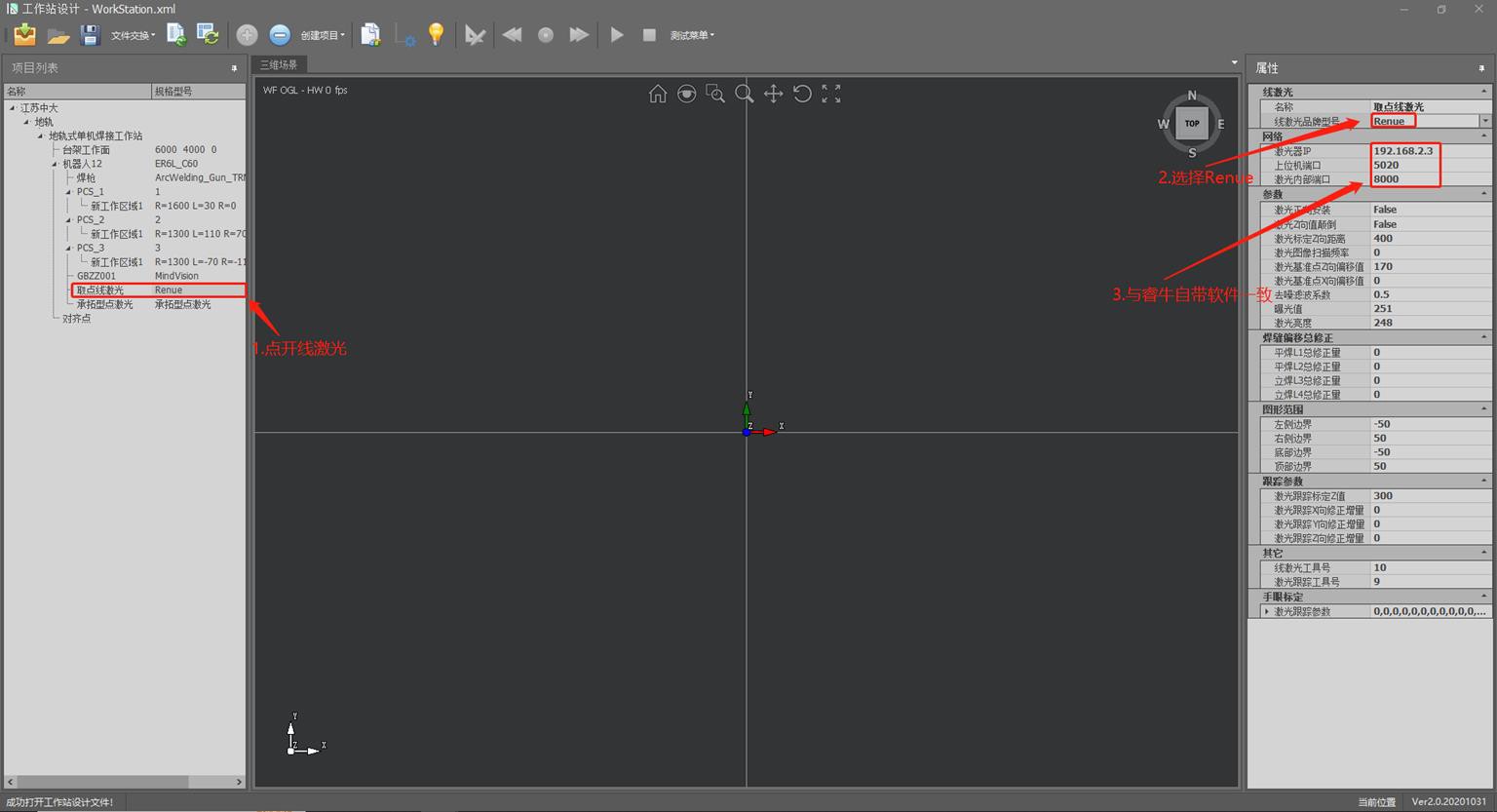
- The name must match and the brand must match.
- Distance from camera to gun tip: fill in according to distance.
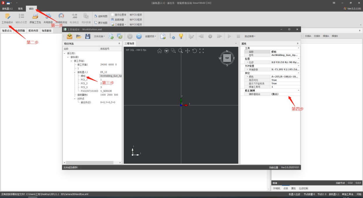
Tool calibration
- Select User\Robot Coordinate System, tool1.
In the tool’s coordinate system, select tool1; The method is TCP & Z, X
direction (six-point calibration), then click calibrate.
- First, locate point P4: align the welding gun guard vertically with the calibration pin and record in the program using line instruction.
- First point: move the robot with 4+, 6+; Then align with the calibration pin and click on teach.
Second point: move the robot with 4-, 6-; Then align with the calibration pin and click on teach.
Third point: run the P4 point program, use 5+ with tilt of about 45°, align with the calibration pin and click teach.
Fourth point: run the program from point P4 and click on teach. Fifth point: use 3+ to raise more than 200mm and click teach.
Sixth point: run the P4 point program, use 1- to move more than 200 mm
and click teach.
- Click Calculate and Save.
65
Tool calibration verification
- Align the tip of the gun to the calibration pin in the 180, 0, 0 posture and record using the line instruction in the program.
- Use 5+ with inclination of approximately -45°; if there are deviations in X or Z, run the previous program.
- In the tool1 tool’s coordinate system, correct the deviation of X in Z (-/+), the deviation of Z in X (-/+), save; do not correct AND.
- Delete the previous program and re-register.
- Use 5+ with inclination of approximately -45°; if the deviation increases, it means that the addition/subtraction is incorrect; Repeat steps 2 through 4 until it lines up with the calibration pin.
- If there is a deviation in Y, do not correct, just align.
- Move 4- until angle A is 0; if there are deviations, check the X, Y, Z values in the monitoring position and note them as comparison values.
- Move the robot to align the tip of the gun with the calibration pin, check the X, Y, Z values in the monitoring position, and calculate the
corresponding differences.
- In the tool1 tool’s coordinate system, modify half of the differences: X corrects X, Y corrects Y, Z corrects Z, and save.
- Check the X, Y, Z values in the monitoring position by comparing them with the reference values; if the difference is halved, the correction was successful; If the difference increases, it means that the addition/subtraction was reversed.Align the calibration plate horizontally using the tip of the gun, then straighten one side.Point the tip of the gun at the center of the calibration plate in the 180, 0, 0 position, as shown in the right figure.
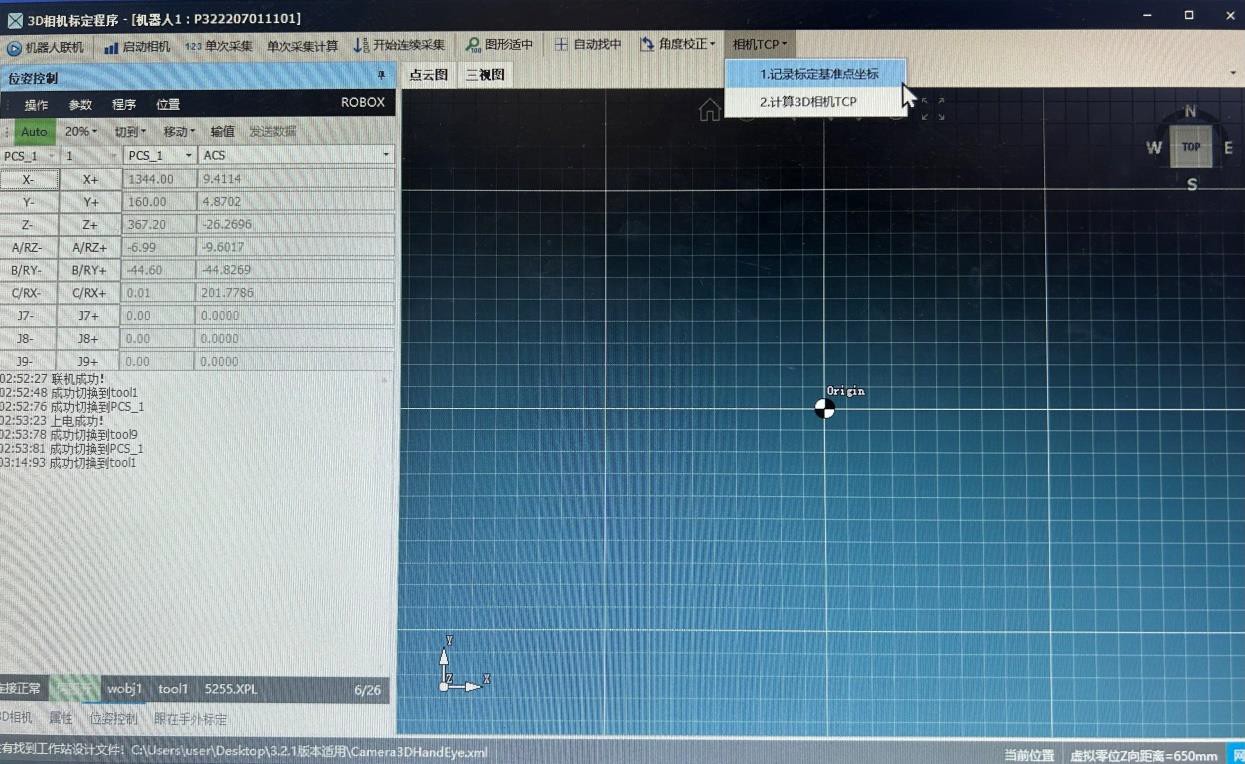
切到tool1才能记录
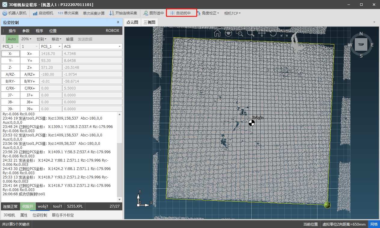
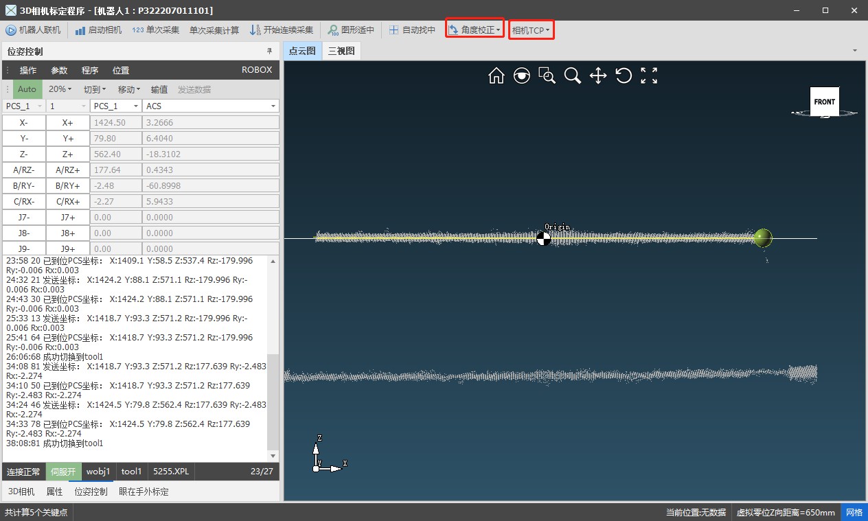
After the automatic search of the center, the image is automatically updated; however, after automatic leveling, it is not automatically updated, so the acquisition and calculation need to be done again.
To upload the calibration data, you need to switch to tool9 in the position control.
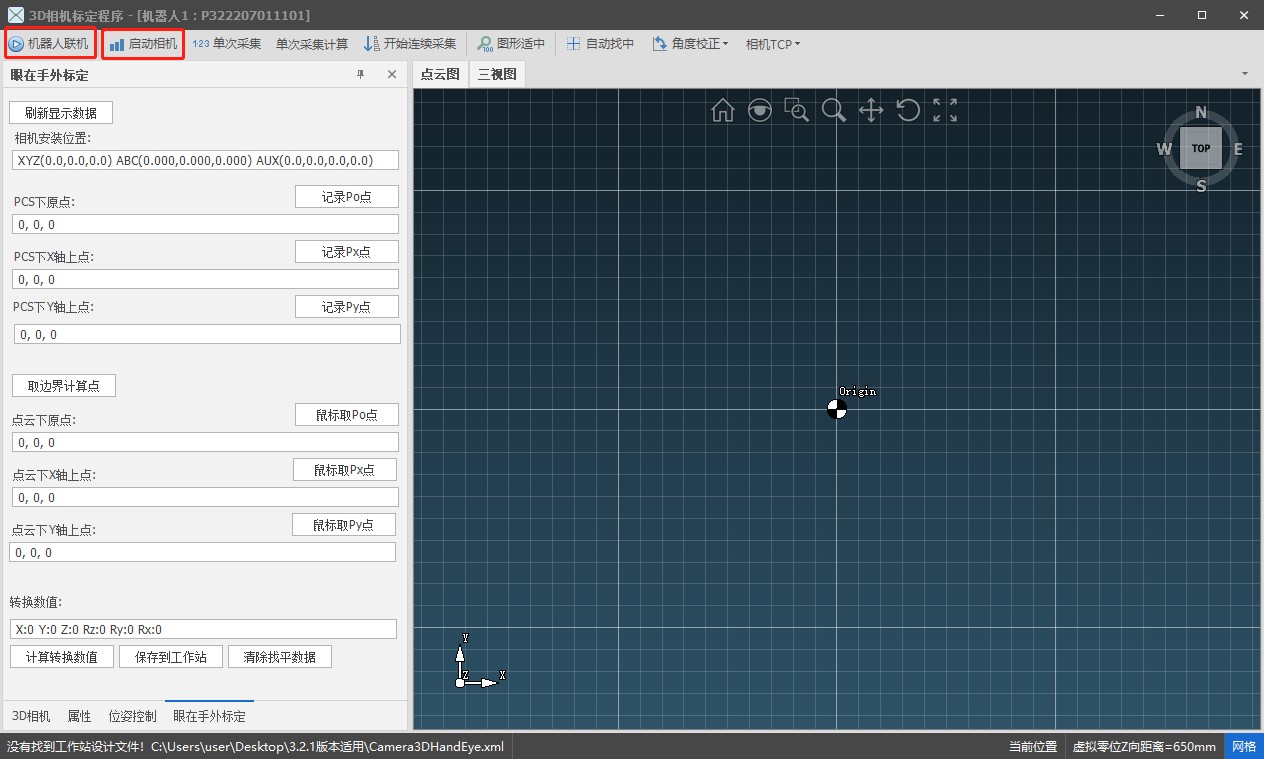
- Align the welding gun in position 135-135, -45, 0 with a point of intersection of three surfaces.Record this point in the program using tool1 and, in editing, change tool1 to tool9.Switch to tool1 and record the calibration reference.Run the tool9 program.One-time acquisition.Under “Acquisition Calculation Selection”: F3 to calculate the intersection of three planes.Automatically search for the center.Since after finding the center the image will not be updated, it is necessary to perform one-time acquisition and calculation with F3.Repeat the previous steps until the location of the center is complete.Switch to tool9, calculate in camera TCP and upload; Verify if the upload to the Teach Pendant was successful.
Linear Laser Calibration
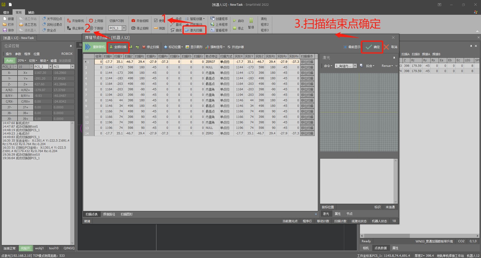
- Linear laser calibration is similar to six-point tool calibration, with the difference that the laser is used to align the calibration points.Open the software → Device Calibration → Device Calibration → Linear Laser Calibration → Continuous Scanning.First, locate the P4 point: align the laser with the calibration point, and on the computer the image should be displayed as in the left figure, with X, Y in the lower left corner approximately 0.1, and the bisector angle at 90°. Record the point in the program.First point: 4+, 6+ with a certain angle, then move the robot to align the laser with the calibration point; on the computer, X, Y ≈ 0.1 and bisector angle 90°, show the point.Second point: 4-, 6- at a certain angle, move the robot to align the laser with the calibration point; on the computer, X, Y ≈ 0.1 and bisector angle 90°, show the point.Third point: 5+ tilted approximately 30° (if the angle is too large the image cannot be captured), move the robot to align the laser with the calibration point; On the computer, the point must match the coordinate source, teach the point.Fourth point: run the program of point P4 and teach the point.Fifth point: 3+ raise more than 200mm, teach the point.Sixth point: run the fourth point program, 1- move more than 200 mm, teach the point.
72
Verification of linear laser calibration
- Align the welding gun with the check points in position 180, – 45, 0, as shown in the figure, and switch to tool1 to record the points in the program.
- Change the program’s tool1 to tool10 and run the program.
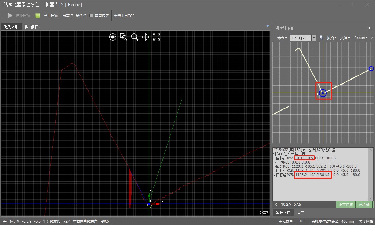
- Click on the lowest point and look at the image on the right side of the software; Adjust axes 1 and 3 of the Teach Pendant until the target point values are approximately 0.1.
- At this time, the PCS value of the target point has an error and must match the points previously recorded in the program; In the tool’s coordinate system, select Tool10 to modify it.
- Subtract the thickness of the plate from the X value of the previous program, change the angle A to 0, and run.
- Modify the PCS of the target point in the same way as
before, but only half of the difference should be adjusted.
2D Camera Calibration
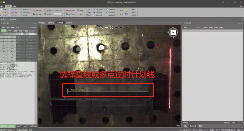
- First, draw an origin and align the tip of the gun; Raise 3+ slightly to avoid subsequent collisions. Record three points in the program: subtract 200 from the X value of the second point and add 200 to the Y value of the third.
- Run step by step to draw the points on the X and Y axes.
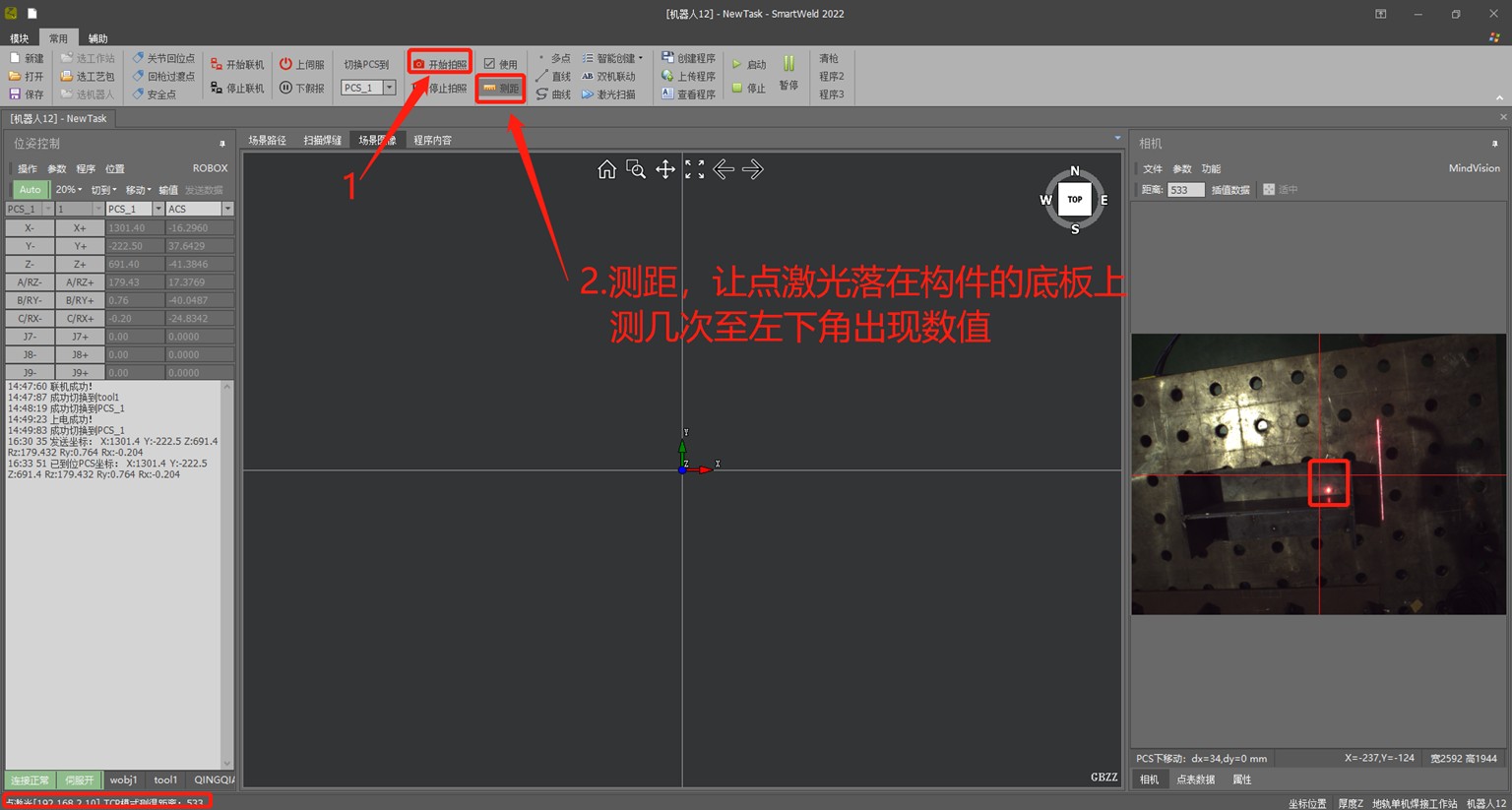
Run the first program, raising the 3+ gun approximately 100 mm. Open the software → plug and turn on → start image capture → measure distance → stop capture → save the image to the camera column → in position control, press Z+ (raise 100 mm each time) → start capture again → …
- Usually about five images are needed, as the subsequent height of
use depends on the calibration range.
- Click Device Calibration → Camera Calibration → Calibration → select the previous images, click Delete Project, → click Insert Image → select the image, → click Mark Points (based on the order of the left image) → drag the marked points to align them with the previously drawn points.
- The camera name must match the name designed on the workstation.
Save to the calibration file → confirm.
Adjusting the welder
- Simultaneously press and hold the storage and wire diameter buttons to access the hidden interface.
- Locate P10 and set it to ON (enable water cooling protection).
- P19: ON for separate mode (current and voltage set separately), OFF for unified mode (default current, welder adjusts voltage automatically).
Updating the card file
- The control cabinet is broken. ElectricityExtractDAKOTA FROM SOUTHTarjeta
| Nombre del archivo | Ubicación | Cambiar contenido |
| herramientaEstándarDo cumento corregido | xpl\tool.xpl | |
| usarfamiliarsentarseEst ándardocumento | xpl\userframe.xpl | |
| Propiedad intelectualArchivo de
direcciones |
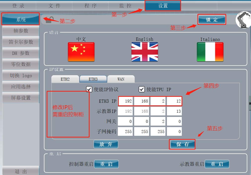
fa\network.cfg | 192.168.2.12 |
| Archivo de información
del robot |
fa\network.cfg | |
| AdjuntarejeArchivo de parámetros | fm\Eje auxiliar | |
| LejosEn el servoelectricidad | fm\controller_config.cfg | elec_man.enable_confirmbutton
= 0; |
| DHArchivo de
parámetros |
fm\DH_Par.cfg | |
| ejecercaFestivalparáme tro | fm\Axes_Par.cfg | seisejecambiarparaarticul ación6 erag.min_str_j[6] =
-720; erag.max_str_j[6] = 720; |
| ponerArchivo de
parámetros de arco |
aplicación\soldadura por arco
\weavescfg.xml |
- FirstDAKOTA FROM ASSORTEll the contents of the cardPreparationCopy to desktop
- deleteExcept for card dropKEYWe content
- Copy the contents of the upgrade package to the card.
- Change server, there is timeexisterbut, havetimeexistFM
- ReviewIntellectual Property
- BundlePreparationParameter Preparation,StandardCorrected Document, AttachmentAxisParameters EnteredDAKOTA OF SURGETarjecta
- Replace the card
- Bundle rpm updateFile is placed on FoilRootRecordInsert Teaching Pendant
- Restart the control cabinet (the control panel screen will refresh and display an error message).
- After rebooting, there will be ErrorIn the control panel, the settings look for
76 the update in the settings. The mold piece, point hitsimply update and restart the control cabinet.
Installation of the torch cleaning station
- Function: Automatic torch cleaning at the end of the welding program or after setting a specific welding program in the cleaning program, to prevent welding slag from clogging the contact nozzle and affecting the welding result.
- Installation: Plan according to the characteristics of the place and the equipment.
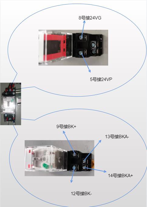
- Connect the black, blue, green, yellow, and red terminals from terminal 1 of the green terminal block of the torch cleaning station downwards, and connect the other end to the control cabinet.
- Connect the black wire to 24VG, and connect the blue, green, yellow, and red terminals from the output terminal 16 onwards to the air inlet tube, which in turn connects to the pressurization pump.
- Adjustments: A torch cleaning program can be inserted or manual alignment can be performed (i.e., align the welding torch with the desired point).
- Configure the first I/O pin for sandblasting.
- Set the second I/O pin for wire cutting.
- Set the third I/O pin for oil spraying. In the common software parameters, turn on the torch cleaning switch, enable the custom program name, enter the name of the torch cleaning file from the control panel, and change the
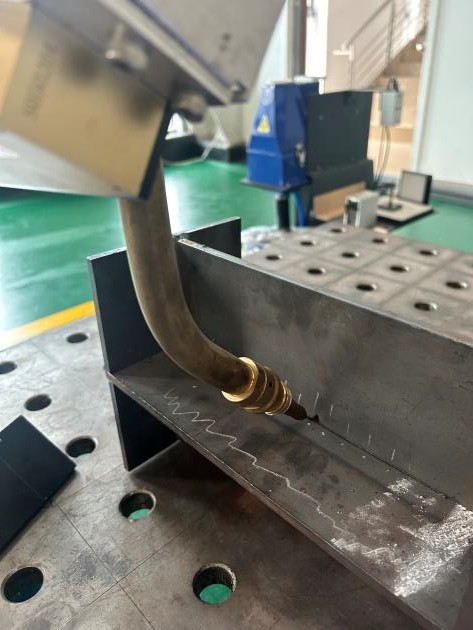
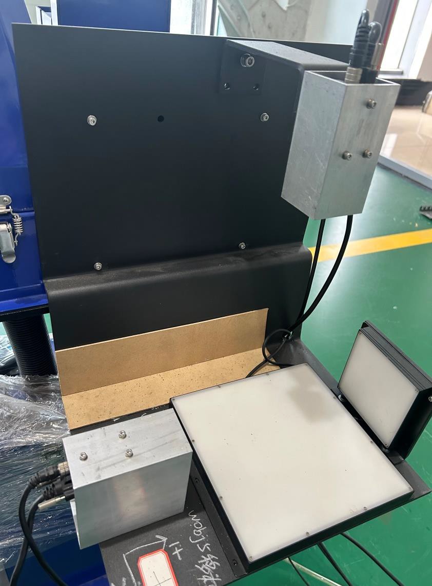
Automatic calibration facility
Function: When the welding torch is collided or long use causes reference shift, it can be
 automatically corrected by software.
Installation:
- Platform, large rear light source, cables, lighting controller, two cameras with their cables, two viewing boxes.Mono-station and linear guide: fix on the robot’s external workstation, with bolts on the chassis.Bridge: fix on the bridge column, with bolts on the side plate.
- Pre-adjust the exposure and focus of the two cameras prior to installation, ensuring clear images and adequate brightness.
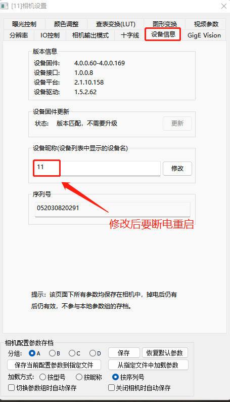
- Open MindVision, select each camera and go into Settings:Device information: modify the camera name; top camera name XY, side camera name Z.Graphic transformation: do not mark mirror, rotation disabled; save. Turning Off and Restarting the Camera.
- Connect the power cable of the rear light source to the lighting controller, then use a quad-core cable to connect the green terminal of the lighting controller to the control cabinet; two positive lines at output and two negative lines at 24VG.
- Turn on the switch on the lighting controller and adjust the brightness with the dial.
- Copy the setting and license files. Key of the welding software to be used to the automatic calibration folder.
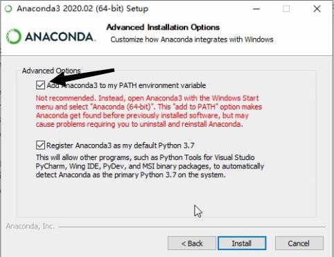
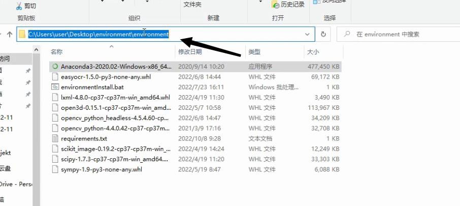
Install Anaconda3 (version must be
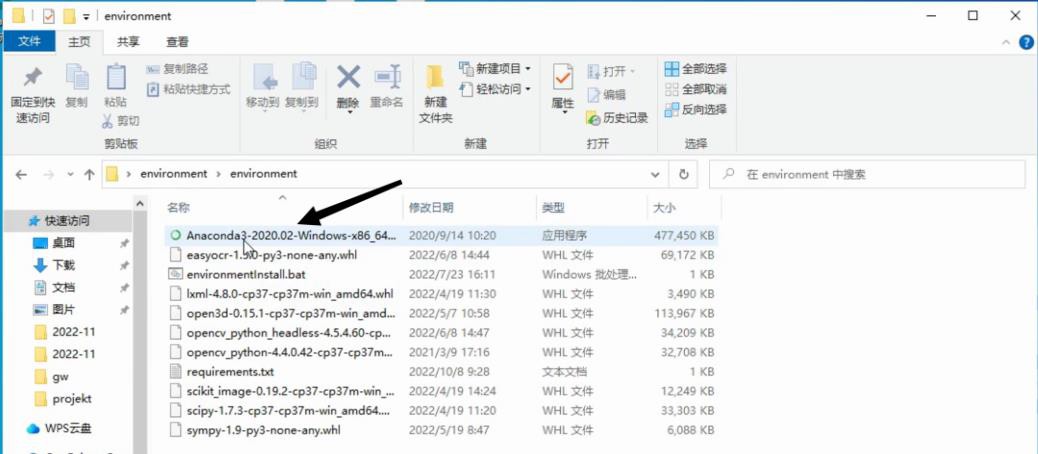 2020.02) on the C drive. Copy the configuration path of the environment (clicking this box with your mouse will bring up
the path).
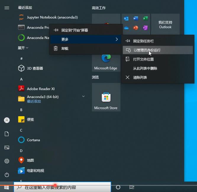 In the start menu, under “Recently Added,” locate “Anaconda Prompt,” right-click, select “More,” and then “Run as administrator.”
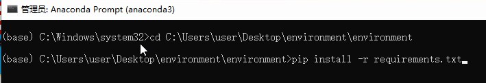
After opening it, type “cd” at the end of the program and paste the path of the environment you just copied.
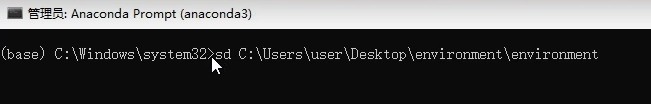
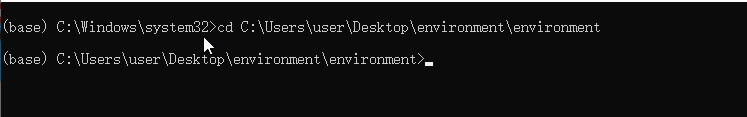 Press “Enter”.
On the second line, type “pip install -r re”.
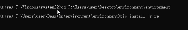
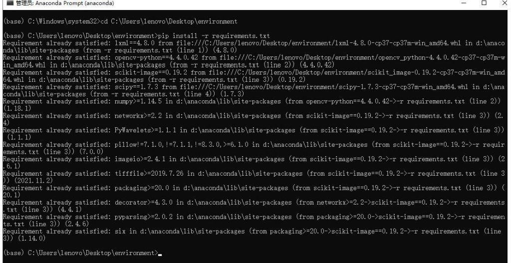 Press the “Tab” key, the system will automatically complete the file.
Press the “Enter” key; If the following screen appears, it indicates that the setup was successful.
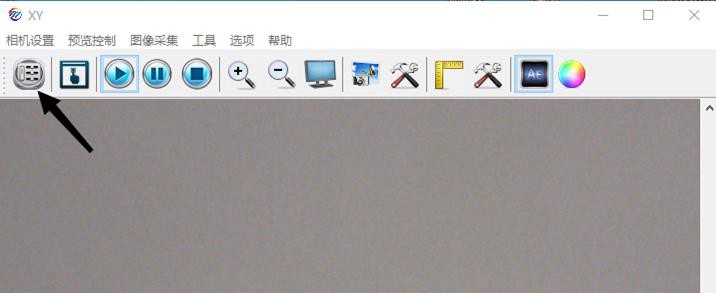
Camera settings
- Open the software, respectively select Camera
→ Camera Settings → Device Information (name the two cameras as XY and Z) → Graphic Transform (do not mark mirror, rotation disabled) → Save