5.4 Sub menu
Sub-menu parameter
In order to achieve an optimum welding result, it is necessary in some cases to make corrections of the arc-length, arc force as well as parameters like pre gas time, post-gas time and slow wire feeding. For details of how to set the Sub-menu parameters, please refer to “Sub-menu parameter set”. Specific sub-menu parameters as Table 5-3-1:
| Item | Parameters | Setting Range | Min. Value | Factory Setting |
|---|---|---|---|---|
| P01 | Burn back time | 0.01~2.00s | 0.01s | 0.08s |
| P02 | Slow wire feeding | 1.0~22.0M/min | 0.1M/min | 1.5M/min |
| P03 | Gas pre-flow time | 0.1~10.0s | 0.1s | 0.20s |
| P04 | Gas post-flow time | 0.1~10.0s / ON | 0.1s | 5.0s |
| P05 | Initial period | 1~200% | 1% | 135% |
| P06 | Crater filler period | 1~200% | 1% | 50% |
| P07 | Transitional period | 0.1~10.0s | 0.1s | 0.2s |
| P08 | Spot welding time | 0.01~9.99s | 0.01s | 2.0s |
| P09 | Welding machine/Robot control selection | OFF/ON | ―― | OFF |
| P10 | Water cooling selection | OFF/ON/ONo/OF1 | ―― | ON |
| P11 | Double pulse frequency | OFF/0.5~5.0Hz | 0.1Hz | OFF |
| P12 | High pulse group arc length adjustment | -5.0~+5.0 | 1 | 0.0 |
| P13 | Double pulse speed offset | 0~2m | 0.1m | 2m |
| P14 | High pulse group duty cycle | 10~90% | 1% | 50% |
| P15 | Pulse mode | OFF/UI/II/UU | ―― | OFF |
| P16 | Fan-on demand cooling time | 5~15min | 5min | 5min |
| P17 | Special 2-step arc start time | OFF/0.1~10s | 0.1s | OFF |
| P18 | Special 2-step arc stop time | OFF/0.1~10s | 0.1s | OFF |
| P19 | Separate adjustment mode | OFF/ON | ―― | OFF |
| P22 | Arcing pulse current | -0.5~5.0 | ―― | 0.0 |
| P23 | Arc start pulse time | -0.5~5.0 | ―― | 0.0 |
| P24 | Short circuit rise rate | -0.5~5.0 | ―― | 0.0 |
| P25 | Short-circuit rising inflection point | -0.5~5.0 | ―― | 0.0 |
| P28 | Analog wire feeder calibration gear | 0~10 | ―― | 5 |
| P29 | Wire feed motor type selection | 0~3 | ―― | OFF |
| P30 | Jog wire feed speed | 0.8~22.0m/min | ―― | 3.6 |
| P54 | Constant voltage arc starting time | OFF/0.1~5.0s | ―― | OFF |
| P55 | Constant voltage crater switch | OFF/ON | ―― | OFF |
| P56 | Wire feed motor current | OFF/0.1~3.0A | ―― | OFF |
Table 5-3-1: Sub-menu parameter
Press the adjustment knob (1) for about 5 seconds, and the parameters will be restored to factory settings.
P01 Burn back time
It is used to burn off excess wire when welding stops.If too long time, the wire will burn back too much with too large melting ball at the end of wire; if too short time,the wire will stick with the workpiece.
P02 Slow wire feeding
After welding starts, the wire feed speed before the welding wire touches the workpiece.With too quick feeding speed, the wire will be easily exploding with failed arc-starting; if the feeding speed is slower than the melting speed, the long arc will cause conductive tip burned.
P03 Gas pre-flow time
Time between start of gas supply and welding.Longer time will cause waste of gas and low efficiency; shorter time will cause air hole during arc-starting.
P04 Gas post-flow time
Longer time will cause waste of gas; shorter time will cause air hole during crater filler period.
P05 Initial period
It is used to set the arc start current and arc start voltage value during aluminum alloy welding to prevent unfused. The default value is 135% of the preset current.
P06 Crater filler period
It is used to set the current and voltage values when welding is closed, and it is used to fill arc craters. The default size is 50% of the preset current.
P07 Transition period
The time cost from starting current to normal welding current and then to post current.
P08 Spot welding time
Choose spot welding process and set the welding time.
P09 Welding machine/Robot control selection
In ON mode, welding parameters can be adjusted by welding machine control panel;in OFF mode, welding parameters can be adjusted by robot/digital communication or analog preset parameters.
P10 Water cooling selection
ON mode: EOA will be appeared after abnormal water flow is detected, the output of the welding machine will stop, and the water cooler will be turned off.
OFF mode: no detection of water flow, the welding machine will not stop and the water cooler will not be turned off when the water flow is abnormal.
ONo mode: when an abnormal water flow is detected, the welding machine will report EOA after the arc stops and the water cooler will be turned off.
OF1 mode: do not detect water flow, turn off the water cooler (limited to the independent control model of the water cooler).
P11 Double pulse frequency
The double pulse welding is added modulated by low frequency pulse and the low frequency pulse between 1.6-2.2 Hz. Compared with single pulse, double pulse has more advantages: no need to swing, welding seam become fish-scaly automatically, the depth and density of the fish-scale welding seam is adjustable; precise control of heat input. In low-current, cool the melting pool,reduce the deformation of the workpiece and the hot cracking tendency. The melting pool can be periodically stirred; grain refinement, hydrogen and other gases are easily precipitated from the pool to reduce the porosity and the welding defects.
Double pulse reference wave form as shown in Fig. 4-4-1. 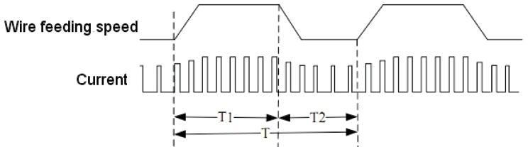
Fig. 4-4-1: Double pulse reference wave form
Choose OFF mode, there is no double pulse, but single pulse mode. If ON, it is double pulse mode, at the same time, you can set low frequency pulse rate. The density and depth of ripple pattern in welding seam can be changed by adjusting low frequency pulse frequency, which is similar to adjustment of T value in Fig.4-4-1.
P12 High pulse group arc length adjustment
In double pulse mode, set high pulse group arc length adjustment to adjust the width of ripple pattern welding seam.
Important! The base arc-length correction with low frequency pulse is controlled by the voltage adjustment knob in the control panel of wire feeder.
P13 Double pulse speed offset
Set the wire feeding in double pulse, the changing arrange of wire feeding means adjusting the depth of ripple pattern.
P14 High pulse group duty cycle
Set ratio between the high pulse group time T1 and low frequency period T in double pulse mode, to adjust the ratio of ledge and groove in the whole ripple pattern.
P15 Pulse mode
In OFF mode, non-fixed frequency mode; in UI mode, fixed frequency mode;in II mode, current control mode;in UU mode, voltage control mode.
P16 Fan-on demand cooling time
Set the time that fan continues to work after power source stops welding.
P17 Special 2-step arc starting time
On special 2-step mode, time for start period. When choose at number, it is time for start period, when reach to this time, will turn to welding standard; when choose at OFF, the function closes.
P18 Special 2 step arc stopping time
On special 2-step mode, time for crater filler time. When choose at number, it is time for crater filler, when reach to this time, will turn to stop welding standard; when choose at OFF, the function closes.
P19 Separate adjustment mode
Analog wire feeder: in ON mode, current and voltage can adjust and display separately; in OFF mode, current and voltage is synergic adjusted, that means voltage will automatically match with current if current is changed.
Digital wire feeder: in ON mode, rotate current adjustment knob to adjust current; rotate voltage adjustment knob to adjust arc length, but voltage is not changed; in
OFF mode, current and voltage is synergic adjusted.
P22 arc starting pulse current
Adjust the arc-starting pulse current, P22-P25 are used to adjust the arc-starting energy, the default value is sufficient.
P23 arc start pulse time
Adjust the action time of the arcing pulse current.
P24 short circuit rise rate
P25 short-circuit rising inflection point
P28 Analog wire feeder calibration gear
The default standard value is 5, the wire feeding speed is proportional to the value, and the speed can be adjusted within a maximum range of ±10%.
P29 Wire feed motor type selection
Select 0 to adapt to the Derui permanent magnet motor, 60-line grating feedback; Select 1 to adapt to the Zhenkang printing motor, back EMF feedback;
Select 2 to adapt to PML printing motor, 60-line grating feedback;
Choose 3 to adapt to the Zhenkang printing motor, 120-line grating feedback.
P30 Jog wire feed speed
Set the jog wire feeding speed, the higher the wire feeding speed, the faster the wire feeding.
P54 Constant voltage arc starting time
Used for constant voltage arc starting time setting. The default is OFF, which disables the constant voltage arc starting function.
P55 Constant voltage crater switch
When OFF is selected, the constant voltage arc crater function is turned off; when ON is selected, the constant voltage arc crater function is turned on. It needs to be used in conjunction with P18. P18 adjusts the arcing time.
P56 Boost wire feeding motor current
It is used to adjust the pulling force of the power-assisted wire feeding motor.The larger the value, the greater the pulling force of the auxiliary wire feeding motor. In general, the 1.2 wire is set to 1.2, and the 1.4 wire is set to 1.4.
Sub-menu parameter adjustment
Enter and exit from the sub-menu and parameters adjustment as Fig. 5-3-2:
Press and hold the “Save” button (20) and the “wire diameter” button (21) at the same time, the sub-menu indicator lights, and enter the sub-menu.
Important! The last parameter to be selected is displayed !The first-time enter shows “P01”.
Press “wire diameter” button (21) to select parameters;
Note! Also can use wire material selection button(s) (23) to select.
Use the adjusting knob to adjust the parameter value.
Important! Adjust the parameters of current percent and arc-length correction firstly before select the parameters of initial standard (P05) and arc stopping standard (P06). Press F2 to choose the desired one and then changes the parameters by adjusting knob (1).
Press “Save” button (20) again and then exit from the sub-menu mode. The indicator (22) is off meaning the exiting from the sub-menu.
![]()
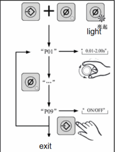
Fig.5-3-2 Sub-menu parameters set
When this series welding machines are working with robot, some parameters will be adjusted from the robot itself, and the welding machine control panel is not allowed an adjustment, please refer to Table 5-3-2.
| Parameters | Parameters that can be adjusted by the welding machine under robot control mode | |
|---|---|---|
| Analogue Interface | Digital Interface (CAN/485/DEV, etc.) | |
While if the operator wants to adjust the parameter from welding machine, please refer to the sub-menu parameter Table 5-3-1, and set the welding machine in panel control mode. Set sub-menu parameter P09 as ON.
| Item | Parameter | Adjustable under robot control mode | |
|---|---|---|---|
| Analog Interface | Digital Interface (CAN/485/DEV, etc.) | ||
| Arc length correction | × | × | |
| Job No. | √ | × | |
| Wire feeding speed | × | × | |
| Welding current | × | × | |
| ARC force/Arc stiffness | √ | × | |
| Wire diameter selection | √ | √ | |
| Wire material selection | √ | √ | |
| Torch operating mode | √ | × | |
| Welding mode selection | √ | × | |
| P01 | Burn back time | √ | × |
| P02 | Slow wire feeding | √ | √ |
| P03 | Pre Gas flow time | √ | √ |
| P04 | Post-Gas flow time | √ | √ |
| P05 | Initial period | √ | √ |
| P06 | Crater filler period | √ | √ |
| P07 | Transitional period | √ | √ |
| P08 | Spot welding time | √ | √ |
| P09 | Welding machine/Robot control selection | √ | √ |
| P10 | Water cooling selection | √ | √ |
| P16 | Fan-on demand cooling time | √ | √ |
| P17 | Special 2-step arc start time | √ | √ |
| P18 | Special 2-step arc stop time | √ | √ |
| P19 | Synertgic mode | √ | √ |
| P22 | Pulse current when start arc | √ | √ |
| P23 | Pulse time when start arc | √ | √ |
| P24 | Short circuit rise rate | √ | √ |
| P25 | Short circuit rise knee point | √ | √ |
| P28 | Analog wire feeder calibration gear | √ | √ |
| P29 | Wire feed motor type selection | √ | √ |
| P30 | Inch wire feeding speed | √ | √ |
| P54 | Super Pulse Switch | √ | √ |
| P55 | Strong pulse speed offset | √ | √ |
| P56 | Weak pulse speed offset | √ | √ |
Table 5-3-3 Welding machine controllable parameters for robot applications
Note!P01 remote reference is valid when the enable bit is turned on.
5.5 Job mode
“Job Mode” enhances the quality of welding, both in semi-automatic and fully automated operation.Traditionally,technical parameters of some repeated operations need to be written down for record. In Job Mode, it is now possible to store and retrieve up to 100 different jobs.
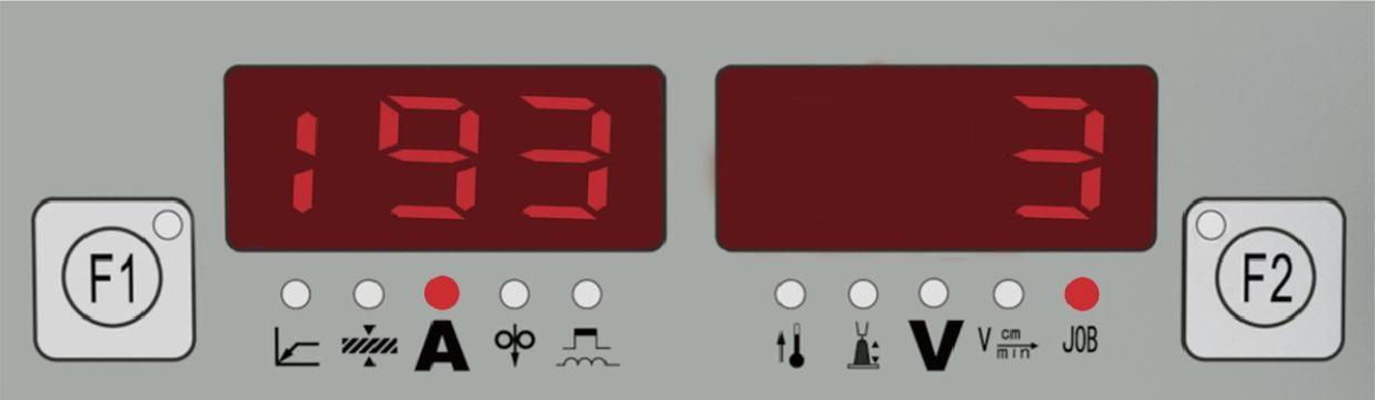
The following symbols are used in Job Mode, on the left displayer:
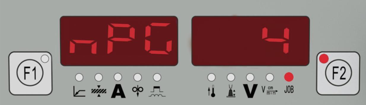
— No job in this program location (only when you try to retrieve a job from this
location, otherwise nPG)
nPG……No job in this program location
Pro Job is being created /copied in this program location
PrG……There is a job in this program location
Stored operating procedures
No job program is saved at the factory. Before calling a job program, the job program must be stored. Follow these steps: 
1. Set the welding parameters that you want to store as a “Job”.
2. Briefly press the Save button (20) to enter into the storage state. The displayed number is the job number that can be stored. 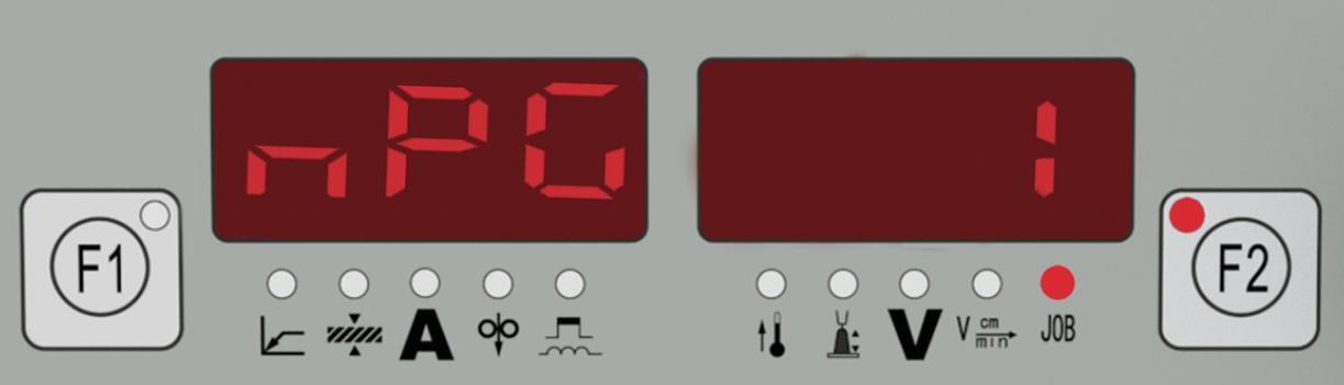
3. Select the program location with the adjustment knob (1), or else leave the suggested program location unchanged.
4. Press and hold the Save button (20). The left displayer reads “Pro” –the job is stored in the program location you have just selected. 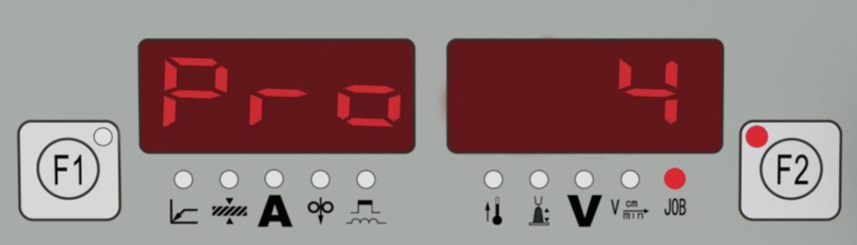
Important! If the selected program location already has a job stored in it, then this existing job will be replaced by the new job.
5. “PrG” appears on the left displayer to indicate that the job is now stored. Release the Save button (20). 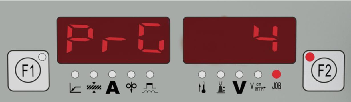
6. Briefly press the Save button (20) to exit from the job menu. 
Recall a job
After storage, all jobs can be recalled and used in job mode.
1. With the “Call” button (19), indicator is on -the last job used is displayed. To view settings programmed in this job, use the “Parameter selection” buttons (2) and (16). The process and operating mode of the stored job are also displayed. 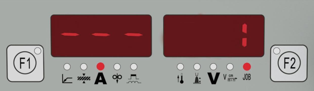
2. With the adjustment knob (1), select the desired job.
3. Press the “CALL” button (19), indicator is off. Exit from the recall mode.