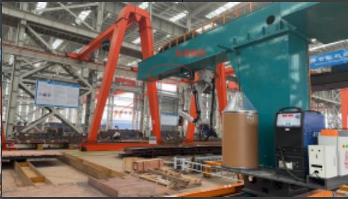


Intelligent robot workstations, intelligent work islands, providing the entire process (cutting, assembly, welding, grinding, inspection, etc.) of intelligent applications for the non-standard metal structure manufacturing industry.
Fans and friends brought components from their factory to our company for inspection and trial welding.
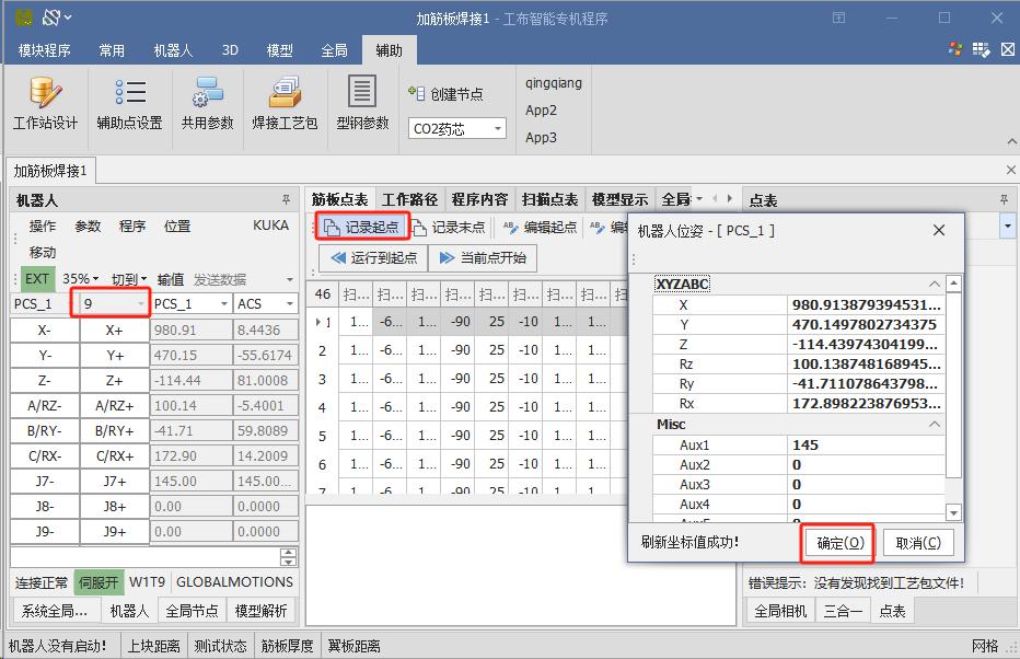
No programming was required.
We could choose any one and place it on our welding workbench.
We only accelerated the unedited content of the following test.
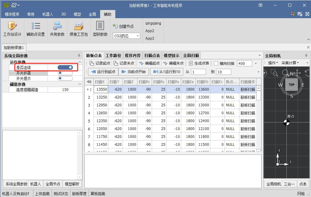
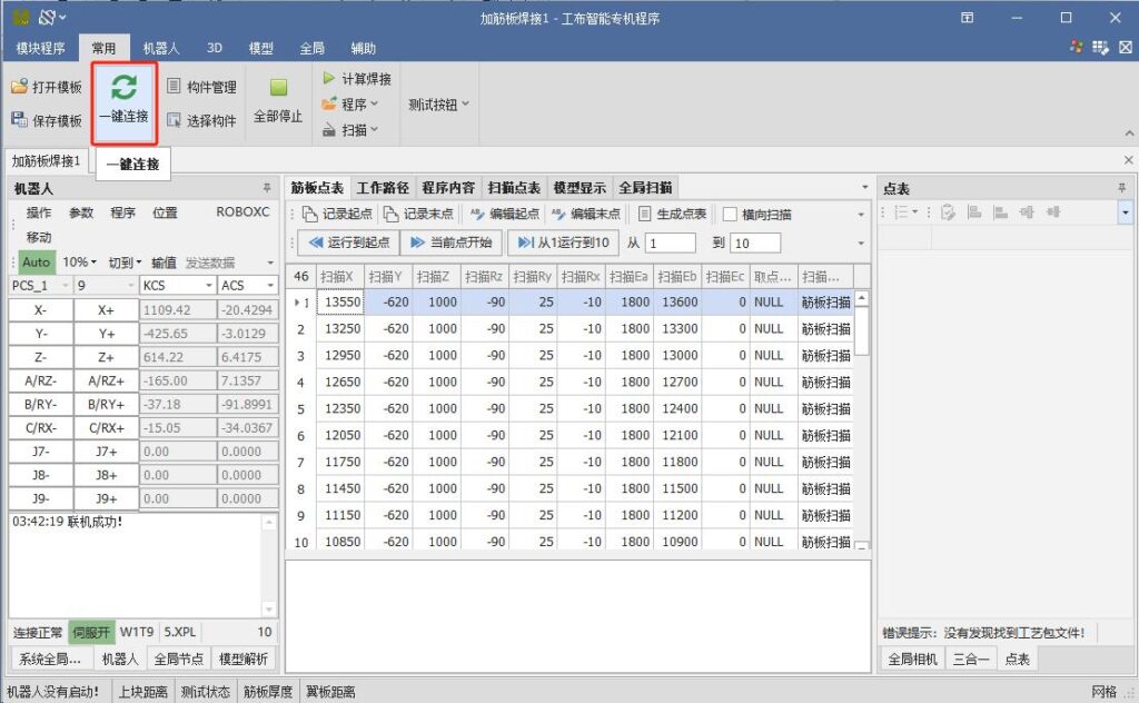
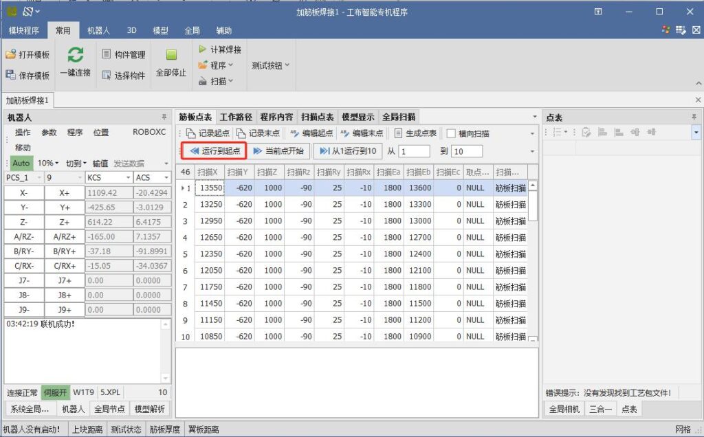
We can see the impact of robot vision on this component.
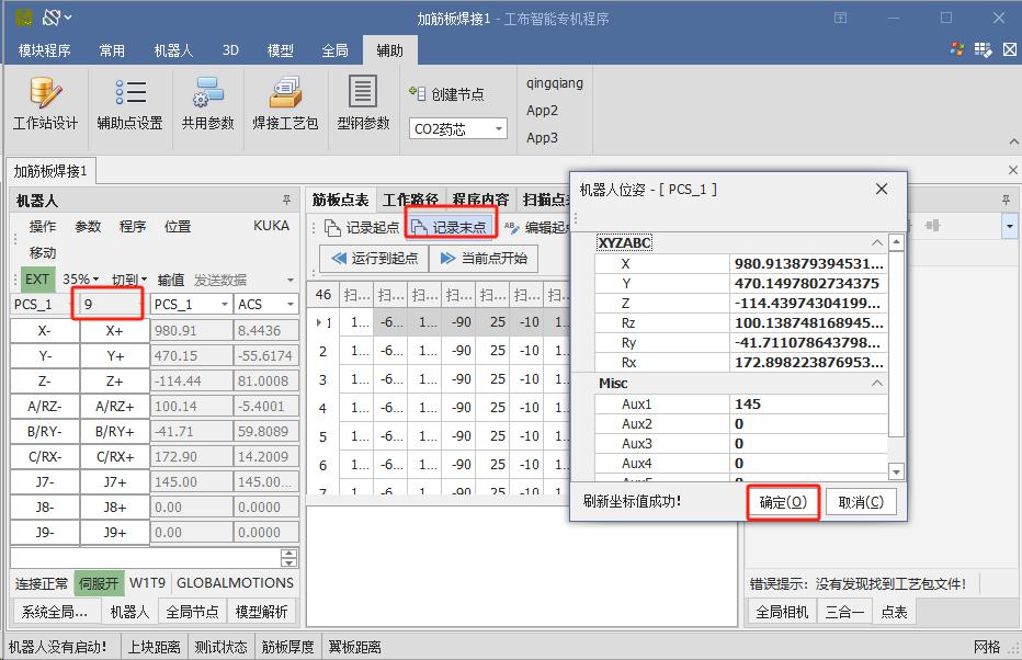
It scanned the welding seams of the outer and inner circles and uploaded the program to the robot.
Then the welding started.
From moving into position to starting the arc, it took about one minute.
The robot continuously welded all the seams on the outer and inner circles.
This is the welded result.
Later, the customer requested to test multi-layer and multi-pass welding.
Compare this welding process with the 600 welders in your factory who work every day.
Which welding looks better?
0 CommentsComment on Facebook
💡 Jensen Huang says China is pulling ahead in the AI race for three compelling reasons. This technological edge is translating directly into industrial innovation, as seen in advanced solutions like dual-robot welding workstations that are redefining efficiency and precision in manufacturing. A clear sign of what's to c#FutureOfManufacturingu#AILeadershipr#industrialautomationation
1 CommentComment on Facebook
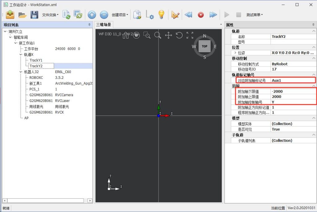
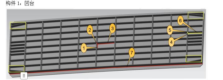
Facing the diversified construction conditions of the power tower industry, our intelligent robotic welding system delivers stable, beautiful weld seams while redefining the production process.
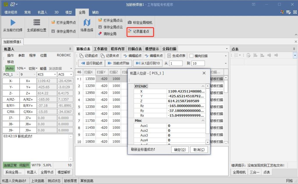
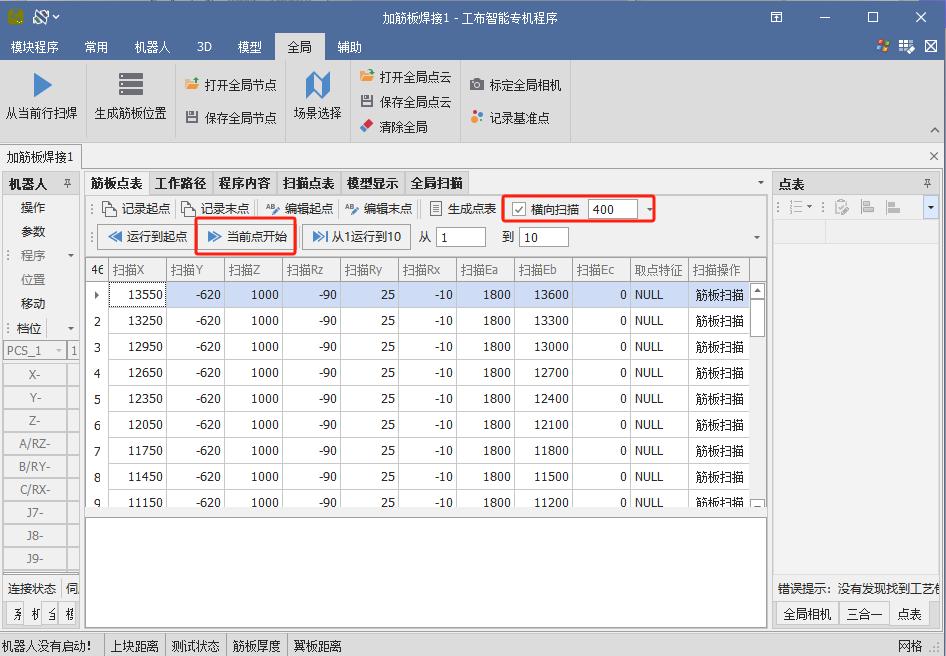
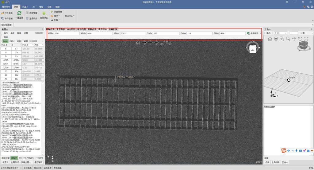
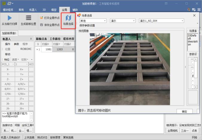
Simply place the components — no model import required.
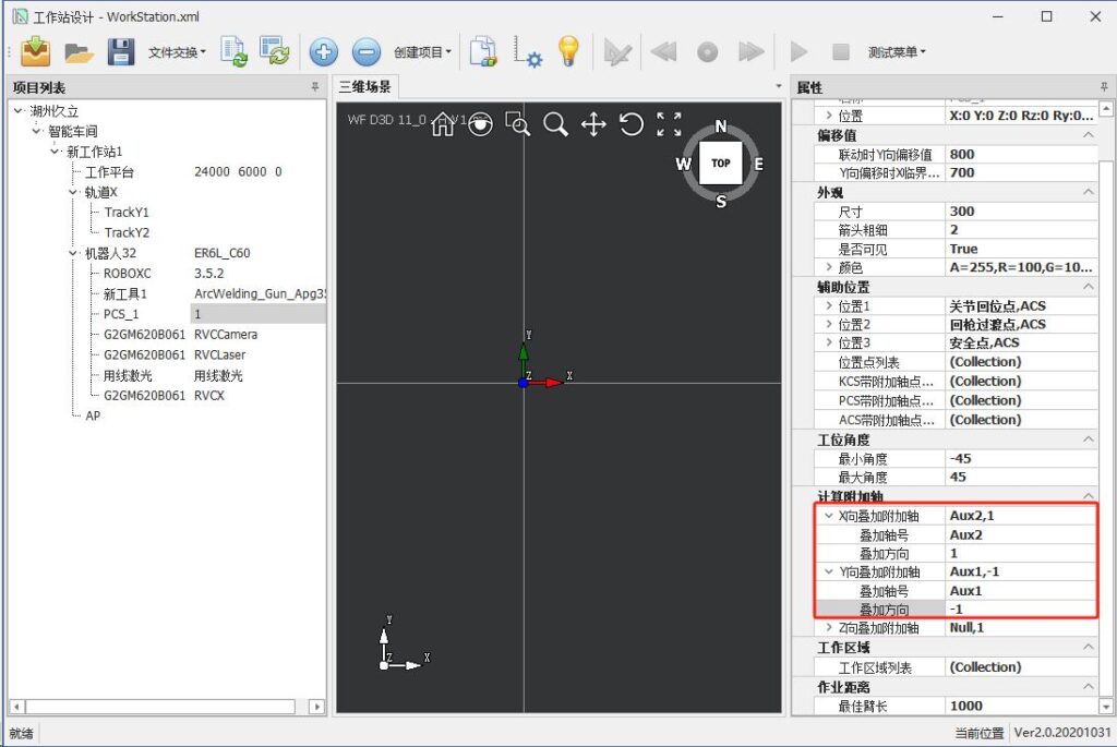
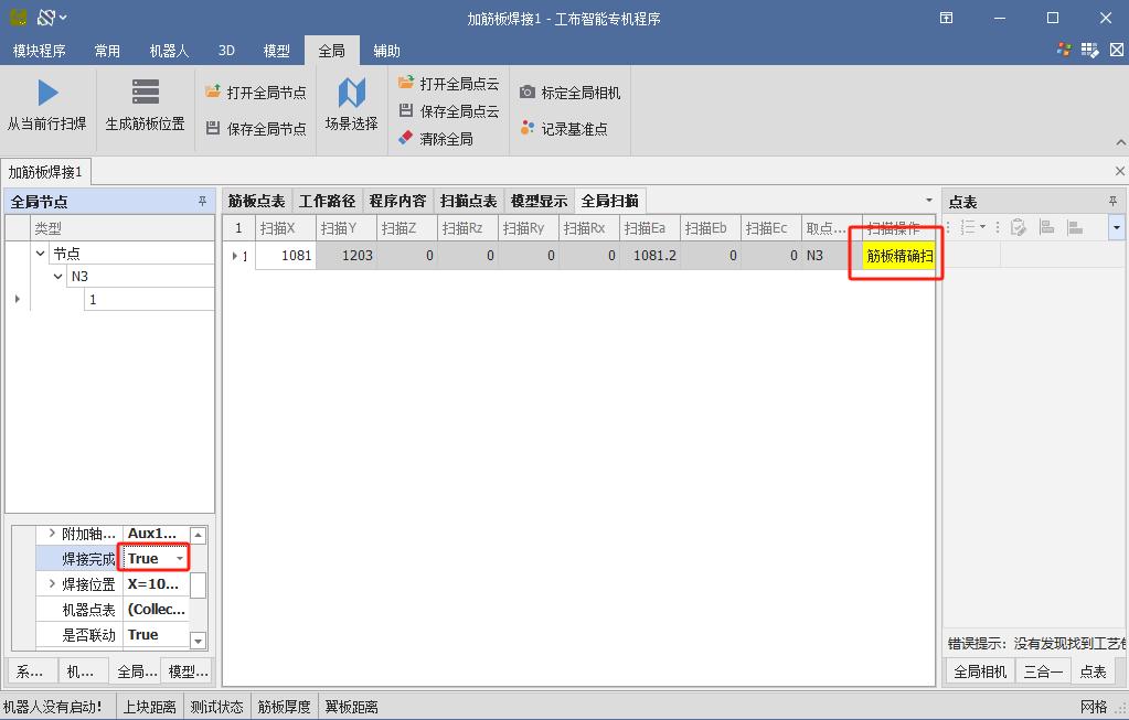
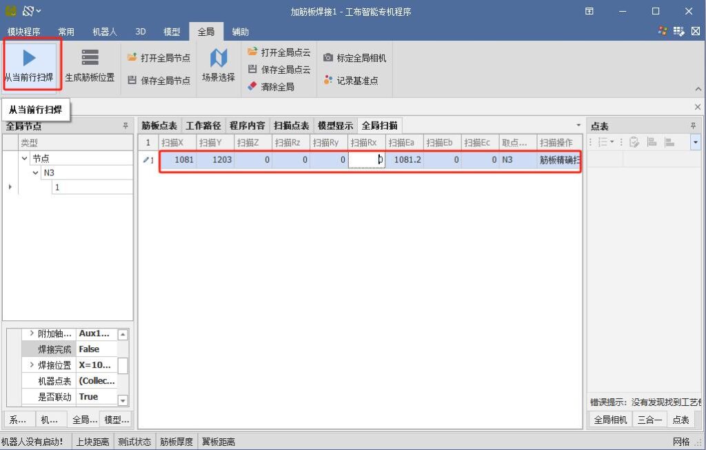
With advanced visual imaging and reverse modeling, the system automatically performs path planning for fully automated welding. Robots operate autonomously along the ground track, completing the entire process from the first weld to the last without human intervention.
After finishing one side, the system automatically turns the component and continues welding on the other side.
One operator can manage multiple intelligent welding lines at the same time.
This solution significantly reduces reliance on highly skilled welders, transforming production efficiency and product quality from difficult-to-control variables into predictable, stable, and manageable outputs.
#roboticwelding #industrialautomation #SmartManufacturing #powertower #WeldingTechnology
0 CommentsComment on Facebook


