Additional Axis Calibration
Step - 1
When an additional axis type is set as a linear plug-in compensation axis, it can be calibrated. The main purpose is to compensate for installation errors and improve the accuracy of the additional axis involved in compensation. The calibration steps of the additional axis are shown below.
1. Configure the additional axis with plug-
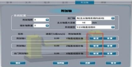
Follow the instructions in the additional axis configuration section of the manual to correctly configure the parameters of the additional axis. Then click the “Calibrate” button for the additional axis, and the system will enter the calibration interface.
Make sure to correctly save the configuration parameters of the additional axis. If the parameters are not saved, you must configure them before calibration.
Additional axis calibration must be performed according to the axis number of the additional axis, that is, calibrate additional axis 1, 2, 3, 4 in order. When calibrating an additional axis, other axes must be disabled.
Step - 2
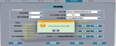
The Additional Axis Cannot Move – Non-plug-in compensation axis has no calibration.
If the additional axis calibration is lost (e.g., after hitting gantry edge or system reset), re-calibration is necessary.
Follow calibration in correct axis number order.
Calibration is invalid if the robot does not move a sufficient distance between points.
2. Set Minimum Distance Between Two Points
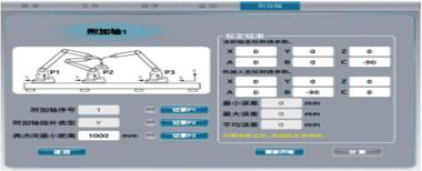
After entering the additional axis calibration interface, set the minimum distance between two points. This value prevents issues caused by too short a distance when teaching calibration points.
If the actual distance moved by the additional axis between two positions is too small, the system will display an error and prevent calibration.
3. Teach Calibration Points
After moving the robot arm to the required position, secure the robot, and click “Record P1” to save the first calibration point.
Then move the tool center point (TCP) to the second and third positions and click “Record P2” and “Record P3” respectively.
Note: The tool must accurately reach each calibration point to ensure correct calibration of the additional axis.
Step - 3
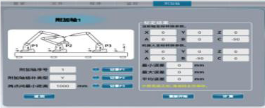
4. Calculate the result.
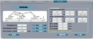
After recording the three points, click the “Calculate” button in the lower right corner.
The calculation result will then be displayed on the interface.
After the calculation is completed, you need to return to the main page to save the data.
5. Directly fill in the calibration results.
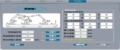
In the calibration result page, the auxiliary axis conversion parameters and the robot coordinate transformation parameters can be directly modified.
After modification, you can directly return to the main page and save the result.
6. Verify the precision of the auxiliary axis calibration.
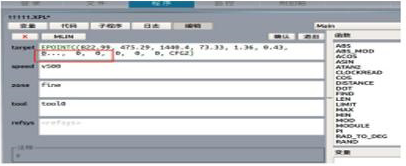
After the auxiliary axis calibration is completed, create a new program, insert several relative motion points between the robot and the TCP to perform fixed-point testing.
Try to modify the coordinates of the calibration point slightly.
The robot, human, and auxiliary axis should be able to run without collisions (pay attention to the robot’s xyz position which should remain unchanged).
During the running process, if the TCP error between the two points is small, the calibration precision is high.


