Oil change in A1
Description
The following instructions describe the gear oil change for this axis. This description applies to floor-mounted robots. If the robot is installed in an inclined or suspended position, it must be ensured that all the oil can flow out. If necessary, the robot may have to be removed and bolted to the floor.
If the robot is installed in an inverted position, the procedure is to be ap- plied analogously, but with the filler and drain holes reversed.
Equipment
The following equipment is required:
| Designation | Article number |
| Set of Allen keys 1.5; 2; 2.5; 3; 4; 5; 6; 8; 10 mm | – |
| Set of Allen keys 12; 14; 16; 20; 24; 30 mm | – |
| Set of combination wrenches 6; 7; 8; 9; 10; 11; 12; 13; 14; 15; 17; 19 mm | – |
| Socket wrench set | – |
| Torque wrench min. 2 Nm to 20 Nm | – |
| Collection receptacle | – |
| Cleaning cloth | – |
| KUKA oil pump | 0000-180-812 |
| Oil drain hose (M18x1,5) assy. | 0000-341-661 |
Material
The following material is required:
| Designation | Article number | Quantity |
| Optigear Synt. ALR 150 | (>>> 12.2 “Aux-iliary and operating materials used” Page 216) | Initial filling quantity: 0.52 l |
Refilling quantity
CAUTION
The quantity of oil drained depends on the draining time and the oil temperature. The refilling quantity is the quantity of oil that was drained from the gear unit at the correct operating temperature and with the cor- rect draining time. This oil quantity must be determined. Only this quan- tity of oil may be used when refilling.
If less than 70 % of the specified oil quantity flows out, flush the gear unit with the determined quantity of drained oil once, then pour in the amount of oil that was drained. If less than 50% of the specified oil quantity flows out (e.g. inclined installation), the flushing operation must be repeated twice. During the flushing procedure, move the axis at jog velocity throughout the entire axis range.
The oil quantities specified in the table correspond to the oil quantities in the gear unit at first filling.
Tightening torques
The tightening torques can be found under: (>>> 12.1 “Tightening torques” Page 215)
These are valid for screws and nuts where no other specifications are giv- en.
Screws of strength class 10.9 and higher as well as screws with test cer- tification may only be tightened once with the rated tightening torque.
When the screws are first slackened they must be replaced with new ones.
Preconditions
- The controller is switched off and secured to prevent unauthorized per- sons from switching it on again.
- The gear unit is at operating
- The screw plugs are freely
Work Safety
CAUTION
High oil and surface temperatures after the robot has stopped op- erating
If the oil change is carried out immediately after the robot has stopped operating, the oil temperature and the surface temperature are liable to be high. Touching them may result in burns.
- Wear protective
Warning
Danger to life and limb due to unintended robot motions Unintended robot motions may result in death, severe injuries and dam- age to property.
- Secure the robot by pressing the EMERGENCY STOP
- Warn all persons concerned before starting to put it back into opera-
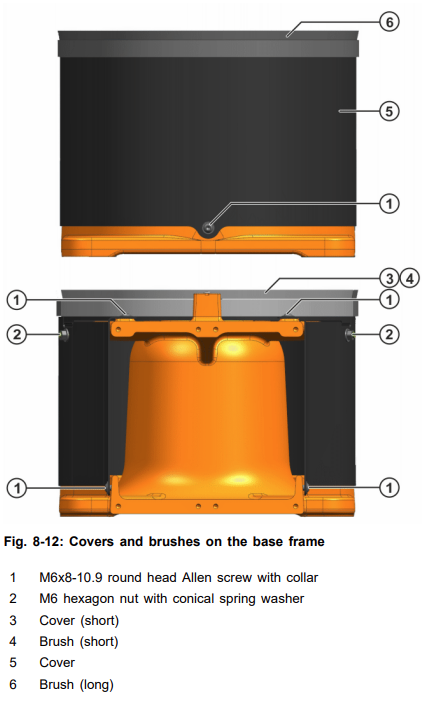
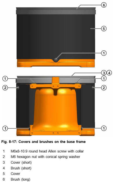
Removing the covers from the base frame
Procedure
- Unscrew 5 M6x8-10.9 round head Allen screws with collar from the
- Unscrew 2 M6 hexagon nuts together with conical spring washer from the cover.
- Remove both covers including brushes from the base
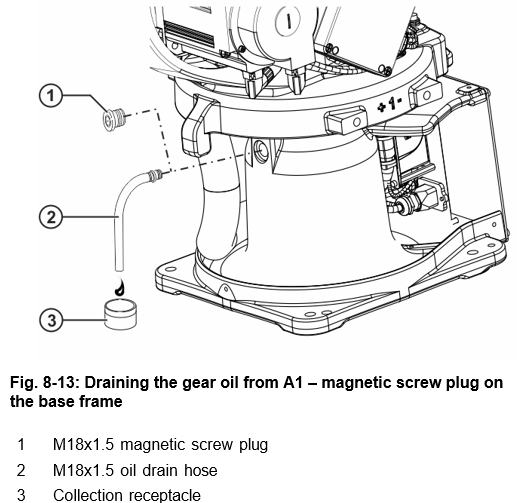
Draining the gear oil from A1
Procedure
- Unscrew the M18x1.5 magnetic screw plug on the base frame and screw in M18x1.5 oil drain hose.
- Place a suitable receptacle under the oil drain
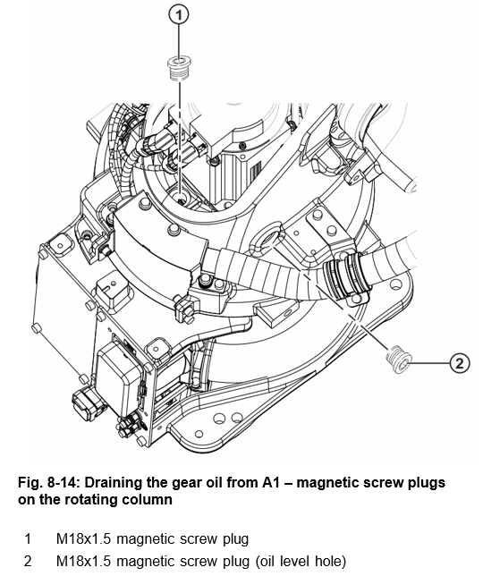
- Remove the M18x1.5 magnetic screw plugs from the rotating column for venting and catch the oil as it drains
- Inspect the magnetic screw plugs for deposits and clean
- Measure the amount of oil drained and dispose of the used oil in ac- cordance with the pertinent regulations.
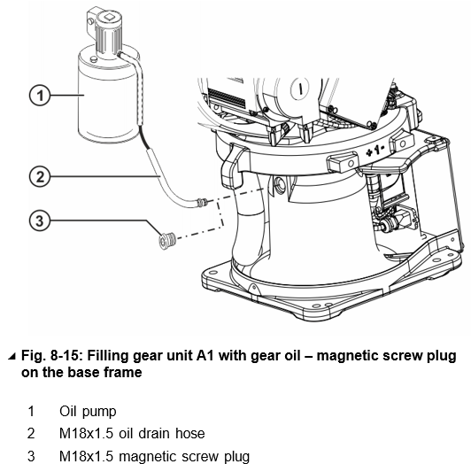
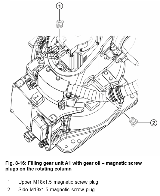
Filling gear unit A1 with gear oil
Procedure
- Screw in the 5 oil drain hose.
- Connect the oil pump to the 5 oil drain hose.
- Fill with gear oil via the 5 oil drain hose up to the lower edge of the side oil level hole.
- Clean the magnetic screw plugs and check the sealing element; ex- change the magnetic screw plug if damaged.
- Insert and tighten both M18x1.5 magnetic screw plugs on the rotating column; MA = 20 Nm.
- Remove 5 oil drain hose and oil pump.
- Insert and tighten the M18x1.5 magnetic screw plug on the base frame; MA = 20 Nm.
Installing the cover on the base frame
Procedure
- Place both covers including brushes on the base frame and align
- Fasten the covers with 2 M6 hexagon nuts including conical spring washers and 5 M6x8-10.9 round head Allen screws with
Concluding work
The following concluding work must be carried out:
- Remove oil
- Visual inspection, check for
- Run the program in T1 mode and look out for
Oil change in A2
Description
The following instructions describe the gear oil change for this axis. This description applies to floor-mounted robots. If the robot is installed in an inclined or suspended position, it must be ensured that all the oil can flow out. If necessary, the robot may have to be removed and bolted to the floor.
If the robot is installed in an inverted position, the procedure is to be ap- plied analogously, but with the filler and drain holes reversed.
Equipment
The following equipment is required:
| Designation | Article number |
| Set of Allen keys 1.5; 2; 2.5; 3; 4; 5; 6; 8; 10 mm | – |
| Socket wrench set | – |
| Torque wrench min. 2 Nm to 20 Nm | – |
| Collection receptacle | – |
| Cleaning cloth | – |
| KUKA oil pump | 0000-180-812 |
| Oil drain hose (M18x1,5) assy. | 0000-341-661 |
Material
The following material is required:
| Designation | Article number | Quantity |
| Optigear Synt. ALR 150 | (>>> 12.2 “Aux-iliary and operating materials used” Page 216) | Initial filling quantity: 0.43 l |
Refilling quantity
CAUTION
The quantity of oil drained depends on the draining time and the oil temperature. The refilling quantity is the quantity of oil that was drained from the gear unit at the correct operating temperature and with the cor- rect draining time. This oil quantity must be determined. Only this quan- tity of oil may be used when refilling.
If less than 70 % of the specified oil quantity flows out, flush the gear unit with the determined quantity of drained oil once, then pour in the amount of oil that was drained. If less than 50% of the specified oil quantity flows out (e.g. inclined installation), the flushing operation must be repeated twice. During the flushing procedure, move the axis at jog velocity throughout the entire axis range.
The oil quantities specified in the table correspond to the oil quantities in the gear unit at first filling.
Tightening Torques
The tightening torques can be found under: (>>> 12.1 “Tightening torques” Page 215)
These are valid for screws and nuts where no other specifications are giv- en.
Screws of strength class 10.9 and higher as well as screws with test cer- tification may only be tightened once with the rated tightening torque.
When the screws are first slackened they must be replaced with new ones.
Preconditions
- The controller is switched off and secured to prevent unauthorized per- sons from switching it on again.
- The gear unit is at operating
- The screw plugs are freely
- The robot is in a position in which all of the oil in this axis can flow
Work Safety
CAUTION
High oil and surface temperatures after the robot has stopped op- erating
If the oil change is carried out immediately after the robot has stopped operating, the oil temperature and the surface temperature are liable to be high. Touching them may result in burns.
- Wear protective
Warning
Danger to life and limb due to unintended robot motions Unintended robot motions may result in death, severe injuries and dam- age to property.
- Secure the robot by pressing the EMERGENCY STOP
- Warn all persons concerned before starting to put it back into opera-
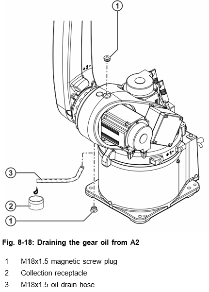
Draining the gear oil from A2
Procedure
- Unscrew the M18x1.5 magnetic screw plug and screw in M18x1.5 oil drain hose.
- Place a suitable receptacle under the oil drain
- Remove the M18x1.5 magnetic screw plug from the rotating column for venting and catch the oil as it drains
- Inspect the magnetic screw plugs for deposits and clean
- Measure the amount of oil drained and dispose of the used oil in ac- cordance with the pertinent regulations.
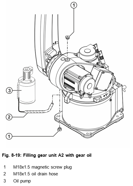
Filling gear unit A2 with gear oil
Procedure
- Screw in the 5 oil drain hose.
- Connect the oil pump to the 5 oil drain hose.
- Fill with the specified amount of oil from the bottom via the 5 oil drain hose.
- Clean the magnetic screw plugs and check the sealing element; ex- change the magnetic screw plug if damaged.
- Insert and tighten the upper M18x1.5 magnetic screw plug, MA = 20 Nm.
- Remove 5 oil drain hose and oil pump.
- Insert and tighten the lower M18x1.5 magnetic screw plug; MA = 20 Nm.
Concluding work
The following concluding work must be carried out:
- Remove oil
- Visual inspection, check for
- Run the program in T1 mode and look out for
Oil change in A3
Description
The following instructions describe the gear oil change for this axis. This description applies to floor-mounted robots. If the robot is installed in an inclined or suspended position, it must be ensured that all the oil can flow out. If necessary, the robot may have to be removed and bolted to the floor.
If the robot is installed in an inverted position, the procedure is to be ap- plied analogously, but with the filler and drain holes reversed.
Equipment
The following equipment is required:
| Designation | Article number |
| Set of Allen keys 1.5; 2; 2.5; 3; 4; 5; 6; 8; 10 mm | – |
| Socket wrench set | – |
| Torque wrench min. 2 Nm to 20 Nm | – |
| Collection receptacle | – |
| Cleaning cloth | – |
| KUKA oil pump | 0000-180-812 |
| Oil drain hose (M18x1,5) assy. | 0000-341-661 |
Material
The following material is required:
| Designation | Article number | Quantity |
| Optigear Synt. ALR 150 | (>>> 12.2 “Aux-iliary and operating materials used” Page 216) | Initial filling quantity: 0.26 l |
Rendering Quality
CAUTION
The quantity of oil drained depends on the draining time and the oil temperature. The refilling quantity is the quantity of oil that was drained from the gear unit at the correct operating temperature and with the cor- rect draining time. This oil quantity must be determined. Only this quan- tity of oil may be used when refilling.
If less than 70 % of the specified oil quantity flows out, flush the gear unit with the determined quantity of drained oil once, then pour in the amount of oil that was drained. If less than 50% of the specified oil quantity flows out (e.g. inclined installation), the flushing operation must be repeated twice. During the flushing procedure, move the axis at jog velocity throughout the entire axis range.
The oil quantities specified in the table correspond to the oil quantities in the gear unit at first filling.
Tightening Torques
The tightening torques can be found under: (>>> 12.1 “Tightening torques” Page 215)
These are valid for screws and nuts where no other specifications are given.
Screws of strength class 10.9 and higher as well as screws with test cer- tification may only be tightened once with the rated tightening torque.
When the screws are first slackened they must be replaced with new ones.
Preconditions
- The controller is switched off and secured to prevent unauthorized per- sons from switching it on again.
- The gear unit is at operating
- The screw plugs are freely
- A2 and A3 are in the following position:
| Robot | A2 | A3 |
| KR 6 R1840-2 | -90° | +90° |
| KR 8 R1640-2 | ||
| KR 10 R1440-2 |
Work Safety
CAUTION
High oil and surface temperatures after the robot has stopped op- erating
If the oil change is carried out immediately after the robot has stopped operating, the oil temperature and the surface temperature are liable to be high. Touching them may result in burns.
- Wear protective
Warning
Danger to life and limb due to unintended robot motions Unintended robot motions may result in death, severe injuries and dam- age to property.
- Secure the robot by pressing the EMERGENCY STOP
- Warn all persons concerned before starting to put it back into opera-
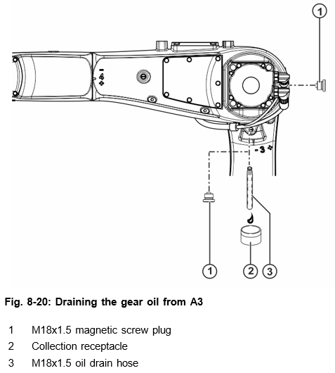
Draining the gear oil from A3
Procedure
- Remove the lower M18x1.5 magnetic screw plug and screw in the 5 oil drain hose.
- Place a suitable receptacle under the oil drain
- Remove the upper M18x1.5 magnetic screw plug (oil level indicator) on the arm for venting and catch the oil as it drains
- Inspect the magnetic screw plugs for deposits and clean
- Measure the amount of oil drained and dispose of the used oil in ac- cordance with the pertinent regulations.
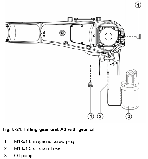
Filling gear unit A3 with gear oil
Procedure
- Screw in the 5 oil drain hose.
- Connect the oil pump to the 5 oil drain hose.
- Fill with the specified amount of oil from the bottom via the 5 oil drain hose.
- Clean the magnetic screw plugs and check the sealing element; ex- change the magnetic screw plug if damaged.
- Insert and tighten the upper M18x1.5 magnetic screw plug (oil level in- dicator); MA = 20 Nm.
- Remove the 5 oil drain hose and oil pump.
- Insert and tighten the lower M18x1.5 magnetic screw plug; MA = 20 Nm.
Concluding work
The following concluding work must be carried out:
- Remove oil
- Visual inspection, check for
- Run the program in T1 mode and look out for
Cleaning The Robot
Description
The robot must be cleaned in compliance with the instructions given here in order to prevent damage. These instructions only refer to the robot.
Equipment
The following equipment is required:
| Designation | Article number |
| Permissible cleaning tools (e.g. cloths, brushes) | – |
Material
The following material is required:
| Designation | Article number | Quantity |
| Cleaning agent: solvent-free, water-soluble, non-flammable, non-aggressive, no steam, no refrigerants | – | – |
Precondition
- The robot controller is switched
- The robot is freely
Notice
The following must be taken into consideration when carrying out cleaning work (material damage may otherwise result):
- Cleaning must be in accordance with the corresponding cleaning in-
- Do not use high-pressure
- Compressed air must not be used to clean bearing and sealing
- It must be ensured that no cleaning agent enters electrical or me- chanical system components.
Cleaning
Procedure
- Shut down the
- If necessary, shut adjacent system components down and lock
- Remove enclosures if this is necessary in order to carry out the clean- ing work.
- Clean the
- Fully remove all cleaning agents from the
- Clean any areas of corrosion and reapply corrosion
- Install any safety equipment that has been
- Put back in place any enclosures that have been
Concluding work
The following concluding work must be carried out:
- Remove cleaning agents and equipment from the workspace of the ro-
- Dispose of cleaning agents in accordance with the pertinent regula-
- Replace any damaged or illegible plates and
- Install any safety equipment that has been removed and check that it is functioning correctly. Only a functional system with all safety func- tions may be put back into operation.


