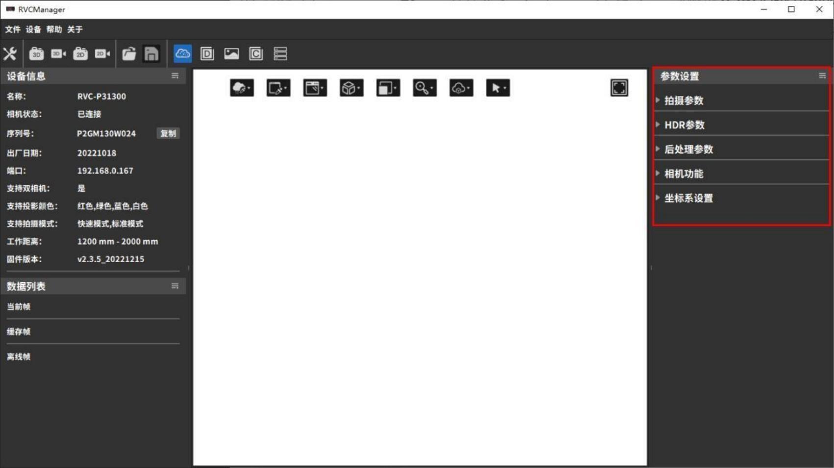
3.4 Parameter settings
This section mainly introduces the components of parameter settings and how to adjust parameters to obtain ideal image data.
Parameter settings are divided into five parts: Shooting Parameters, HDR Parameters, Post-Processing Parameters, Camera Functions, and Coordinate System Settings, which can be adjusted to improve point cloud capture quality.
3.4.1 Preliminary preparation and precautions
Precautions
- Please check whether the camera is within the calibrated working range. Avoid operating the camera outside the calibration range, as this will affect point cloud quality and accuracy.
- Avoid strong direct light in the camera’s operating environment, such as sunlight or spotlights.
- Check whether the measured sample is made of colorless transparent material.
- Do not bump the camera or disassemble/adjust it manually.
- Remove the protective film from the lens and the projector. If the lens or projector is dirty, clean it promptly with lens paper and alcohol.
- Keep the camera and the measured object stationary during shooting; avoid handheld shooting.
Criteria for Evaluating Shooting Quality
A high-quality point cloud should meet the following conditions:
- The point cloud and depth map have no obvious missing areas, with a high fill rate of valid points within the field of view.
- There are no significant floating noise points in the point cloud.
- The point cloud data accurately represents the measured object, without noticeable distortion or bending.
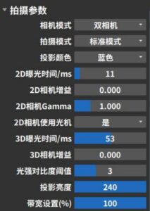
3.4.2 Shooting parameters
Shooting parameters are mainly used to adjust the original image and point cloud effects collected by the camera. The parameter options that can be set are related to the type of camera connected. The following figure takes the shooting parameters of a binocular grayscale camera as an example.
Camera Mode
Monocular cameras cannot select camera modes, while binocular cameras can choose between left camera, right camera, or binocular mode.
In binocular mode, the point cloud is the intersection of the point clouds captured by the left and right cameras. Depending on the object’s position, angle, lighting, and other conditions, different camera modes can be selected based on shooting needs.
| Left camera shooting | Right camera shooting | Dual camera shooting |
|---|---|---|
 |  |  |
Shooting Mode
The RVC-P/I/X series cameras have two shooting modes: Fast Mode and Standard Mode.
Fast Mode increases shooting speed by reducing the number of projections, shortening both projection and processing time by approximately 30% compared to Standard Mode.。
| Fast Mode | Standard Mode |
|---|---|
 |  |
The RVC-G series laser cameras have two shooting modes: High Precision Mode and Anti-Interference Mode.
Anti-Interference Mode builds upon High Precision Mode by increasing the number of shots and using specific algorithms to filter out ambient light. This effectively solves interference from strong ambient light on structured light, enhancing anti-interference capability.
| High Precision Mode | Anti-interference mode |
|---|---|
 |  |
Projection Color
For RGB projector cameras, the projector color (Red/Green/Blue/White) can be switched in binocular mode to improve shooting performance. This function is not applicable in monocular mode.
Typically, objects reflect light wavelengths close to their own color and absorb complementary colors. It is not recommended to use light source colors that the object easily absorbs during shooting. Choosing an appropriate light source color can create sufficient contrast between feature areas and their surroundings, capturing more detailed features. For example, the yellow workpiece in the image absorbs blue light, so it is recommended to set the projection color to red.
| The object being photographed is yellow | Grayscale camera + red light projection | Grayscale camera + blue light projection | Grayscale camera + white light projection |
|---|---|---|---|
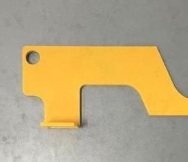 | 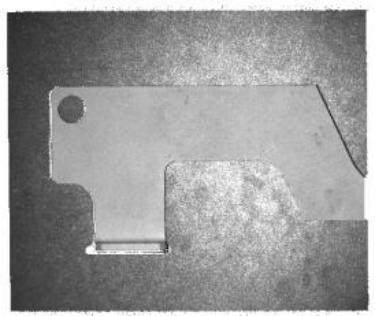 |  |  |
2D Capture Settings
2D shooting parameters are related to the type of camera. RVC series cameras are equipped with grayscale cameras as standard. If you need to shoot with a color camera, please contact customer service.
| Camera Type | Main debugging parameters | Reference rules for parameter adjustment |
|---|---|---|
| 2D exposure time, 2D camera gain, | ||
| Grayscale Camera | 2D Camera Gamma, 2D Camera | Usually, when the 2D image is too dark, you can increase the 2D exposure and 2D gain, and turn on |
| Use optical machine | 2D camera optics; when the 2D image is too bright, you can reduce 2D exposure and 2D gain. | |
| 2D Gamma is rarely used and it is recommended to keep the default value. | ||
| 2D exposure time, 2D camera gain, | ||
| Color Camera | 2D Camera Gamma, 2D Camera | Common problems and solutions for 2D image parameter adjustment can be found in Section 4.4。 |
| Use light machine, automatic white balance |
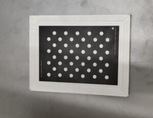
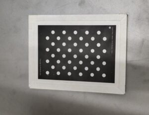
After setting the 2D parameters, click 2D Shooting or 3D Shooting to view the shooting effect of the 2D image. Take the calibration board in the figure below as an example, and refer to the table below for the shooting effect.
| Normal shooting | Image is too dark | Image is too bright | |
|---|---|---|---|
| Point Cloud | 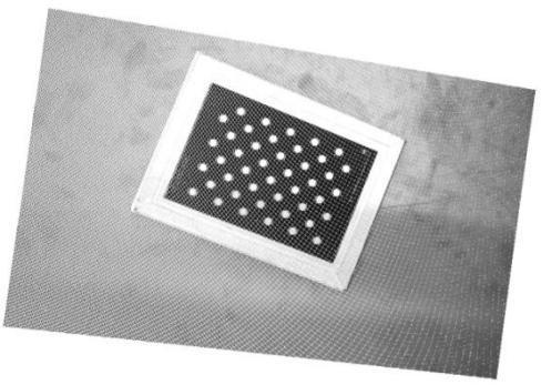 | 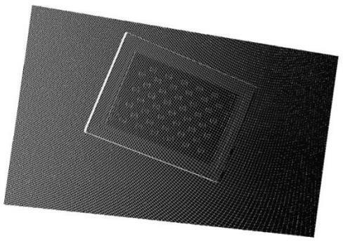 | 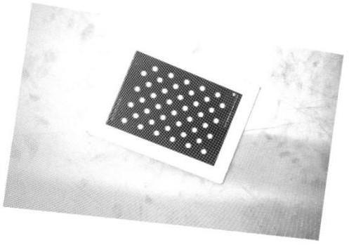 |
| 2D Image | 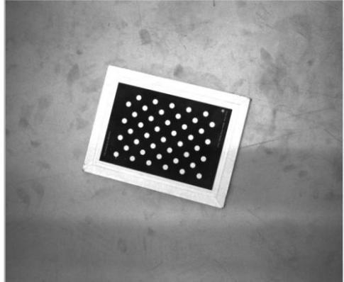 | 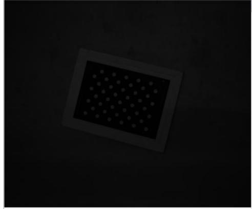 | 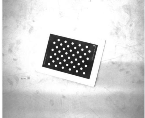 |
Detailed explanations and adjustment examples for each parameter are as follows.
2D Exposure Time: Adjusts the brightness of the 2D image by changing the exposure time. The larger the value, the brighter the image. Both underexposure and overexposure can cause loss of image details.
| 2D exposure time 30 ms | 2D exposure time 80 ms | 2D exposure time 100 ms |
|---|---|---|
 |  |  |
2D Gain:The brightness of the 2D image is adjusted by controlling the sensitivity of the camera’s photosensitive device to light. The greater the gain, the more sensitive it is to light.
| 2D Gain 5 dB | 2D Gain 11 dB | 2D Gain 16 dB |
|---|---|---|
 |  |  |
2D Camera Gamma:Gamma correction is used to expand the details of the dark tones of the image and correct the brightness deviation. The default gamma value is 1, and it does not need to be adjusted in general. Usually, when the gamma correction value is less than 1, the highlight part of the image is expanded and the dark tones are compressed; when the gamma correction value is greater than 1, the highlight part of the image is compressed and the dark tones are expanded.
| 2D Gamma 0.5 | 2D Gamma 1 | 2D Gamma 1.5 |
|---|---|---|
 |  |  |
2D Camera Use of Projector: When capturing 2D images, you can choose whether to turn on the projector for supplementary lighting. Turning on the projector makes the 2D image brighter and does not affect the point cloud.
| Shooting without light camera turned on | Turn on the light camera to shoot |
|---|---|
 |  |
3D Capture Settings
| Adjustment Steps | Main Adjustment Parameters | Reference rules for parameter adjustment |
|---|---|---|
| 3D exposure time, 3D camera gain | ||
| Point Cloud, Depth Map | Benefit, HDR additional exposures, | Usually, when the point cloud is too dark, you can increase the 3D exposure, 3D gain, and projection brightness. |
| Filming | HDR exposure time, light intensity comparison | And turn on the 2D camera light machine; when the point cloud is too bright, you can reduce the 3D exposure, 3D |
| Degree threshold, projection brightness, etc. | Gain, projection brightness. If the color and material of the objects in the shooting scene are very different | |
Post- processing | ||
Can perform confidence denoising and clustering Post-processing such as denoising and smoothing | If the image is large or has reflective areas, you can use HDR mode to shoot. |
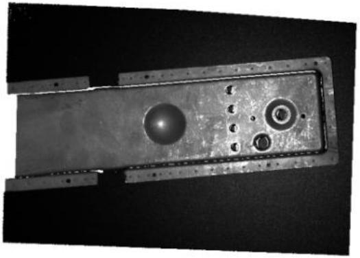
First, perform a test shot using the default parameters. By viewing the solid-color point cloud or depth map, you can quickly assess point cloud loss. Blank areas in the solid-color point cloud and black areas with depth value NAN in the depth map both indicate point cloud loss.
Using the calibration board in the image below as an example, the shooting results can be referenced in the following table.
| Normal shooting | Underexposure | Overexposure | |
|---|---|---|---|
| Point Cloud | 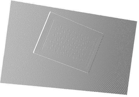 | 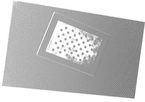 | 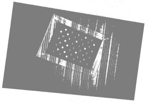 |
| Depth Map | 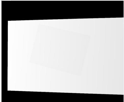 |  | 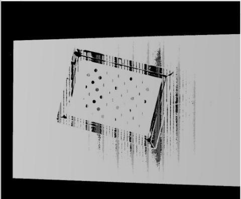 |
Detailed explanations and adjustment effects for each parameter are as follows.
3D Exposure Time: Adjusts the integrity of the point cloud and depth map by modifying the exposure time during 3D shooting. It needs to be tuned according to the actual situation, as both underexposure and overexposure can cause point cloud loss.
The range of 3D exposure time settings available for RVC cameras depends on the model and configuration, and should be based on the range displayed in the software interface.
| 3D exposure 11 ms | 3D exposure 28 ms | 3D exposure 100 ms |
|---|---|---|
 |  |  |
3D Camera Gain: Adjusts the quality of the point cloud and depth map by controlling the sensitivity of the camera’s photosensitive components to light. Higher gain increases light sensitivity but also makes the camera more sensitive to noise, which can enhance point cloud brightness but may also increase point cloud noise.
| 3D Gain 0 dB | 3D Gain 2 dB | 3D Gain 10 dB |
|---|---|---|
 |  |  |
Number of Scans: This parameter applies only to the RVC-G series laser cameras and sets the number of scans during shooting in anti-interference mode. The principle is to merge multiple frames of image sequences obtained from multiple scans according to certain rules and methods to improve image quality. Generally, the higher the number of scans, the stronger the resistance to ambient light interference and the more image details can be captured, but the shooting time will be extended.
| Scan times 2 | Scan times 4 |
|---|---|
 |  |
Light intensity contrast threshold: The light intensity contrast threshold is used to adjust the signal strength in the raw data captured by the camera. When ambient light or reflected light is strong, this option can be used to enhance the integrity of the point cloud and depth map. The default value is 3, and it generally does not need to be adjusted.
| Light intensity contrast threshold 0 | Light intensity contrast threshold 3 | Light intensity contrast threshold 10 |
|---|---|---|
 |  |  |
Projection brightness: Adjusts the projection brightness value of the camera’s optical system during photo capture. The projection brightness setting range is 1 to 240, with a default value of 240. The higher the value, the brighter the projection brightness.
| Projection brightness 31 | Projection brightness 83 | Projection brightness 240 |
|---|---|---|
 |  |  |
Bandwidth settings
Used to adjust the bandwidth of the camera. The setting range is 30%~100%. The smaller the value, the slower the transmission speed. The default value is 100%.
3.4.3 HDR parameters
The HDR function is mainly used to adjust the integrity of the point cloud and depth map, improving the point cloud quality of black light-absorbing objects and reflective objects. In scenes where the tested sample has significant color differences in materials, a single exposure may not be able to accommodate all samples.
The HDR function can provide additional 3D exposure to simultaneously meet the shooting requirements of items with different colors and materials. The HDR parameter options depend on the type of connected camera. The following image shows the HDR parameters for a laser camera as an example.
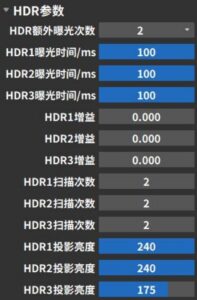
HDR additional exposure count has three options: 0, 1, and 2, which respectively mean no HDR, use 1 additional 3D exposure, and use 2 additional 3D exposures. The exposure time, gain, number of scans, and projection brightness for each exposure can be adjusted. The correspondence between the exposure sequence and the parameters set in the interface is shown in the table below.
| Operation | Exposure sequence | Corresponding parameters | ||||
|---|---|---|---|---|---|---|
| HDR additional exposures | Exposure time | Gain | Number of Scans | Projection brightness | ||
| No HDR | Only 1 impression | 0 | Set directly in “Shooting Parameters” | |||
| Use 1 additional 3D exposure | First exposure | 1 | HDR1 exposure time /ms | HDR1 Gain | HDR1 scan times | HDR1 Projection Brightness |
| 1st additional exposure | HDR2 exposure time /ms | HDR2 Gain | HDR2 scan times | HDR2 Projection Brightness | ||
| Use 2 additional 3D exposures | First exposure | 2 | HDR1 exposure time /ms | HDR1 Gain | HDR1 scan times | HDR1 Projection Brightness |
| 1st additional exposure | HDR2 exposure time /ms | HDR2 Gain | HDR2 scan times | HDR2 Projection Brightness | ||
| 2nd additional exposure | HDR3 exposure time /ms | HDR3 Gain | HDR3 scan times | HDR3 Projection Brightness | ||
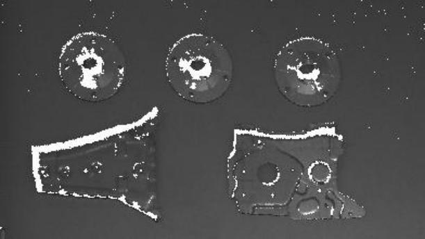
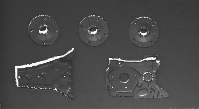
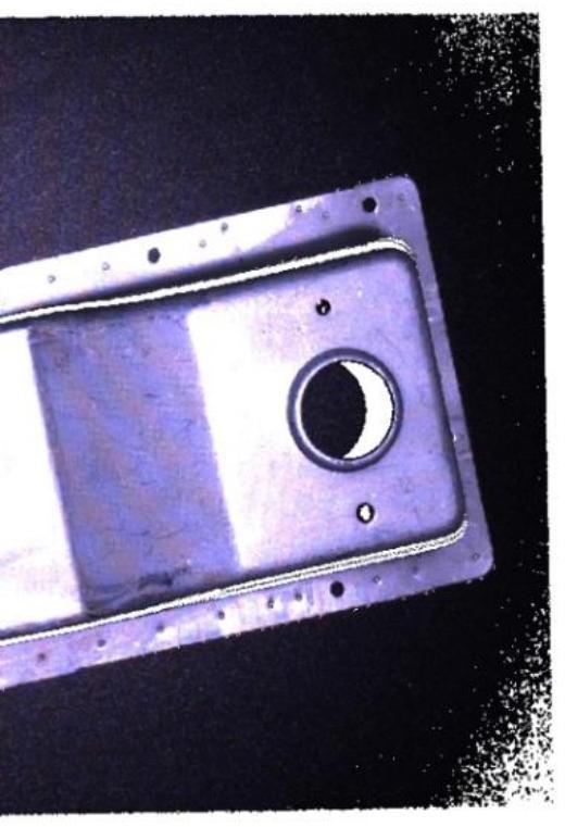
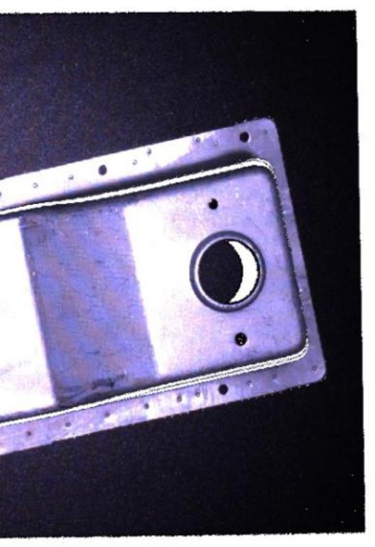
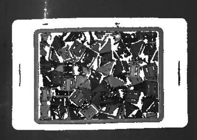
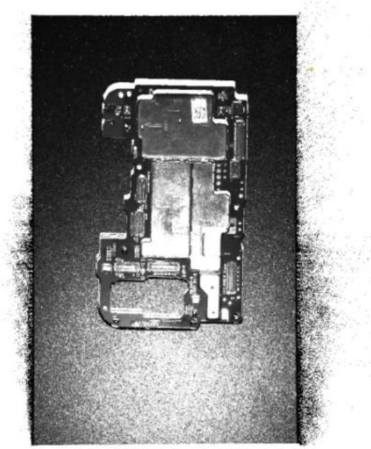
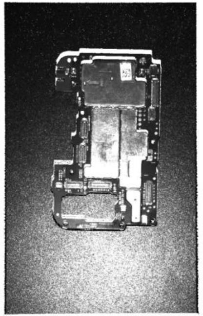
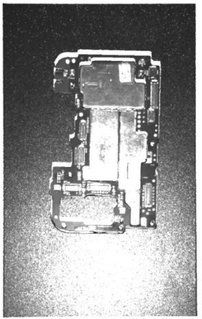
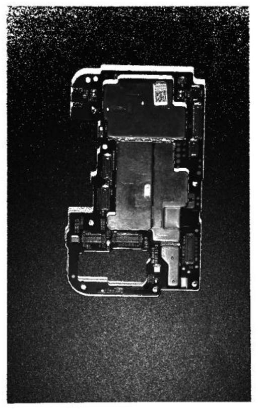
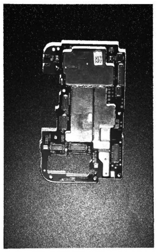
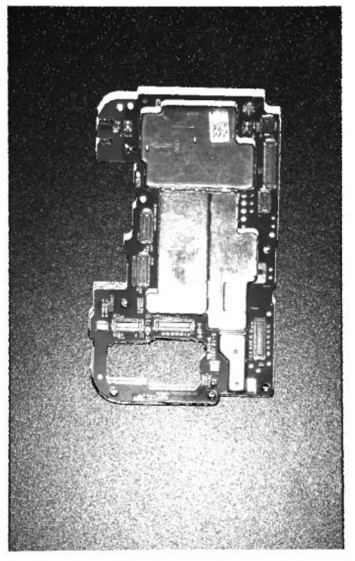
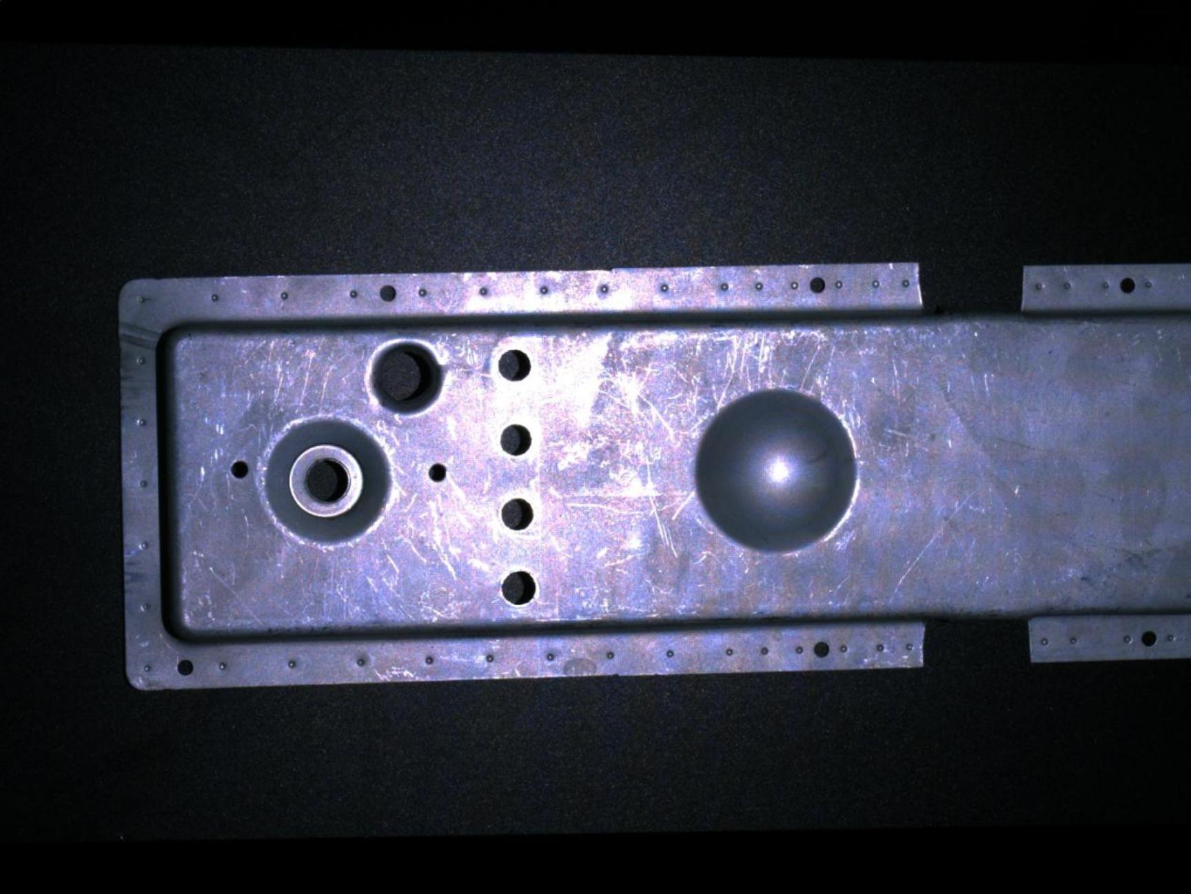
Taking the following shooting scene containing black light-absorbing objects and metallic reflective items as an example.
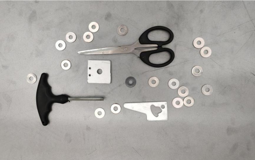
| Single exposure, black parts are underexposed | Single exposure, light colors and reflective parts are overexposed | HDR function 2 additional exposures to synthesize a complete point cloud |
|---|---|---|
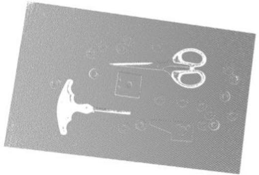 | 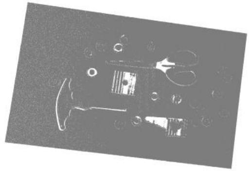 | 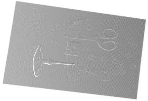 |
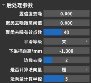
3.4.4 Post-processing parameters
Post-processing parameters are mainly used for noise reduction, smoothing, downsampling, and other post-processing of the generated point cloud, facilitating viewing and application. The configurable parameter options depend on the type of connected camera. The following image shows the shooting parameters for a binocular grayscale camera as an example.
The denoising function includes three methods: confidence denoising, clustering denoising, and edge denoising. The specific functions are as follows:
Confidence Denoising
By adjusting the confidence threshold, noise reduction can be performed based on the point cloud filtering function of confidence. This function mainly targets situations such as insufficient stripe intensity and incorrect stripe intensity caused by multiple reflections. Users can first view the confidence range of the entire field of view in the point cloud display window, then select an appropriate confidence threshold. Points below this threshold will be filtered out. The operation example is as follows:
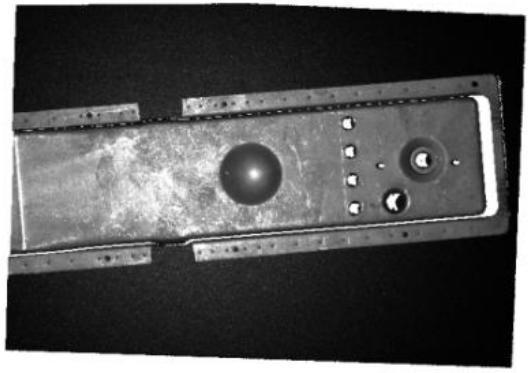
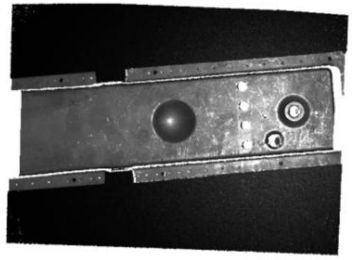
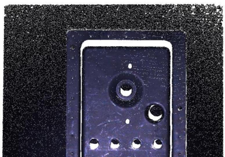
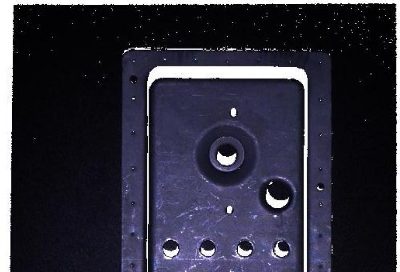
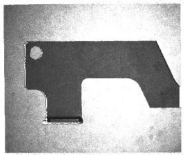
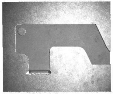
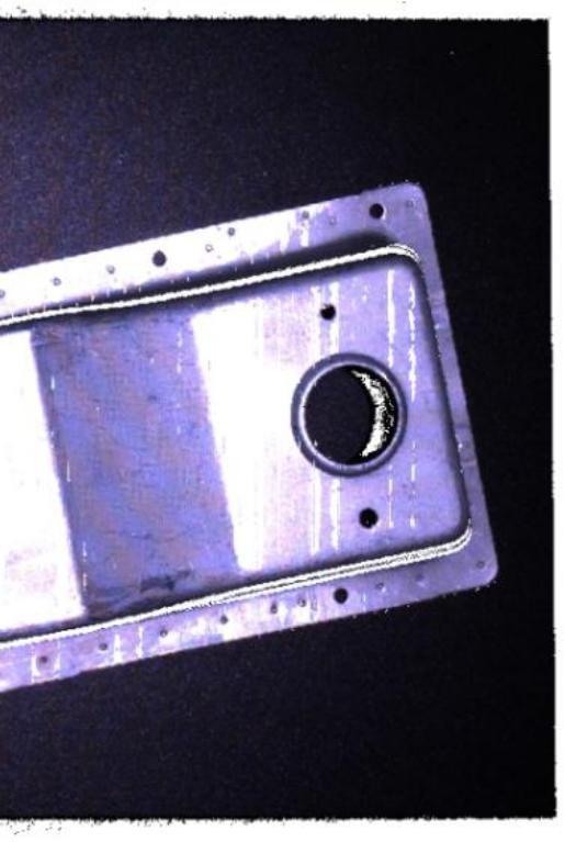
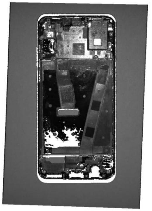
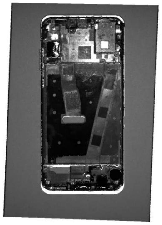
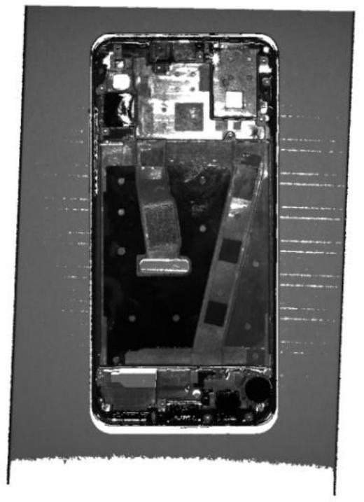
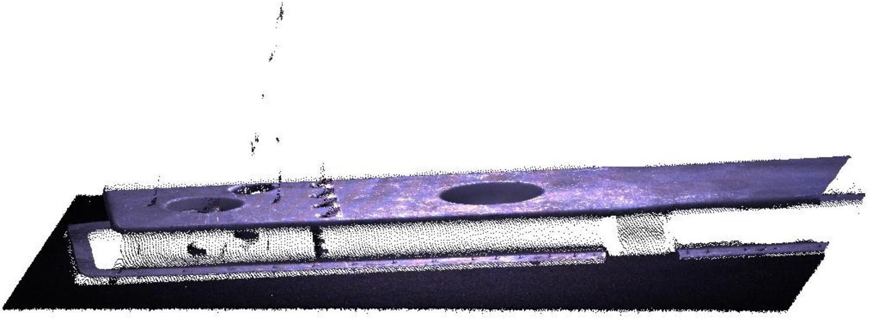
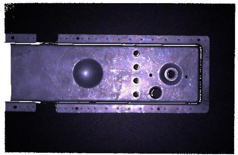
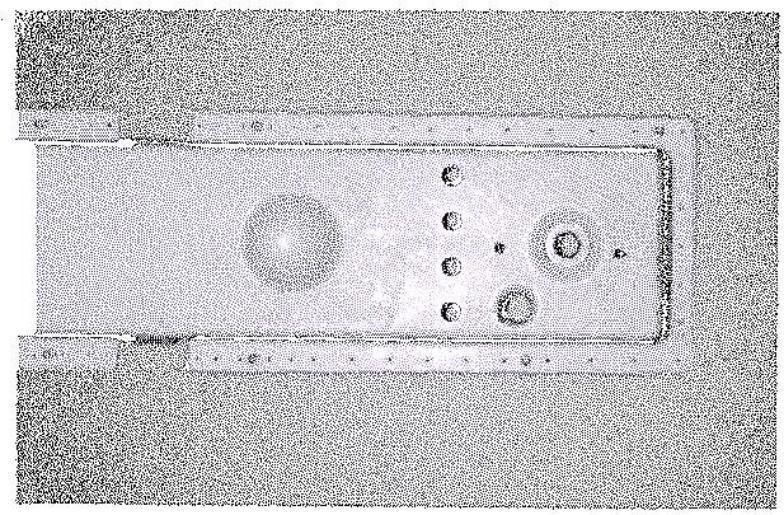
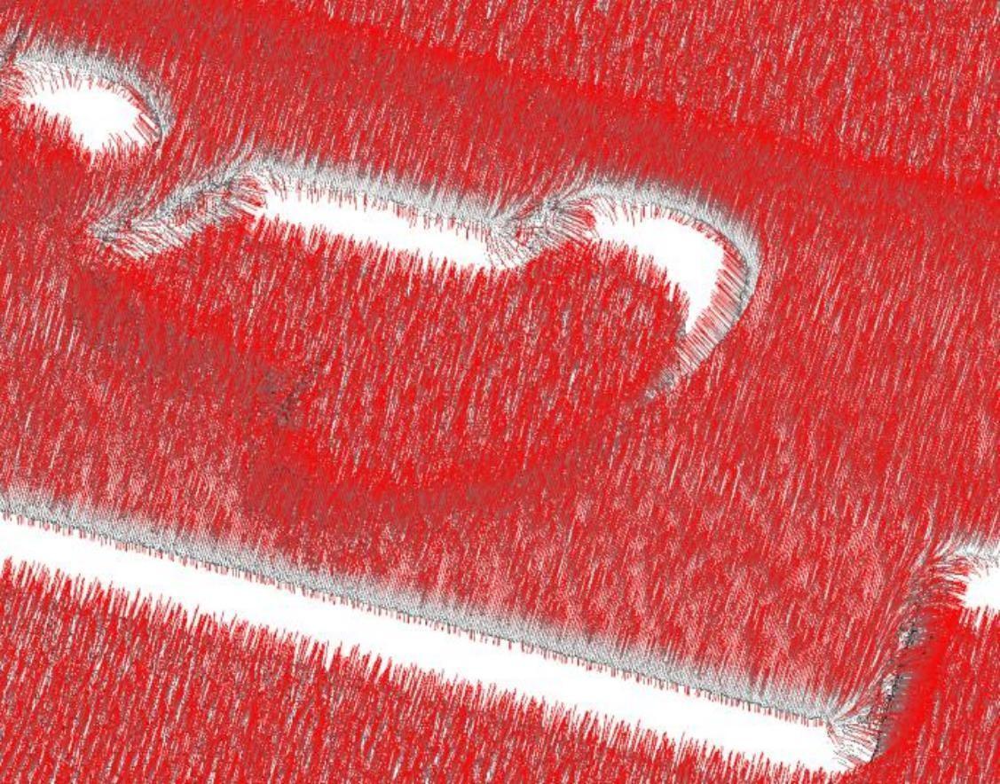
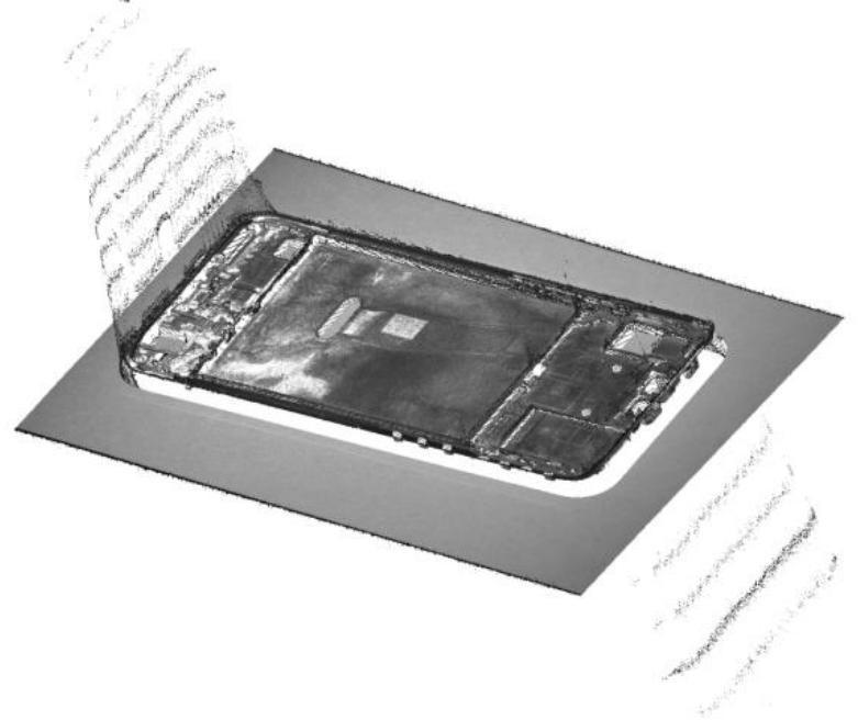
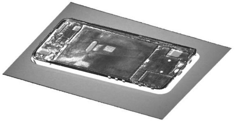
- As shown in the figure below, in the metal part point cloud, there are abnormal flying noise points at the circular hole, which is inferred to be the error of stripe intensity caused by reflection.
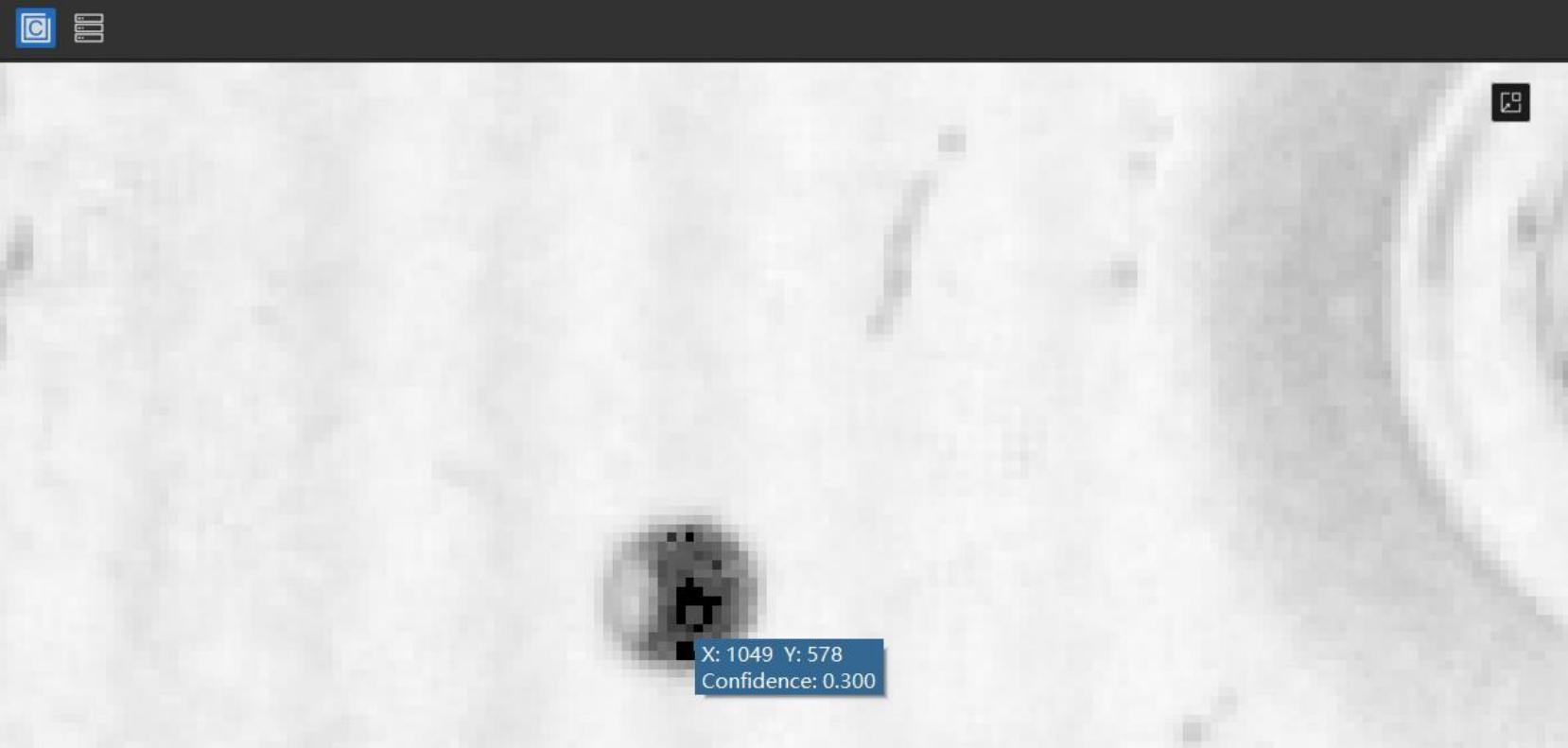
- Open the confidence map and locate the approximate position of the reflection anomaly points, where the confidence is 0.300. Using this as a reference, the confidence denoising threshold can be set above 0.300, such as 0.310. Typically, such noise points correspond to the darker color areas in the confidence map.
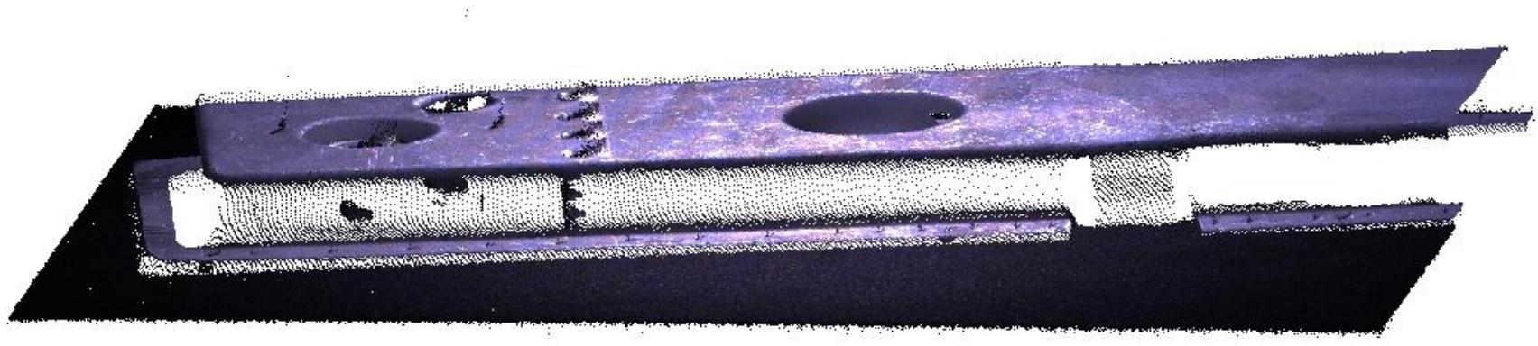
- Re-shooting in 3D shows that the noise in the reflections has been improved.
Clustering denoising
The clustering denoising function can remove abnormal isolated and clustered point cloud noise points and has two parameters: distance threshold and minimum number of valid points. Its principle is: based on the density of points, the original point cloud is divided into several small regions (i.e., clusters). If the number of points in a small region is low, the entire region is considered noise and removed.
Clustering denoising distance threshold: Used to measure the density of points and cluster the point cloud. The smaller the distance threshold, the stronger the denoising effect; however, if set too small, many valid points may be mistakenly deleted. When the distance threshold is 0, clustering denoising is not performed.
Clustering denoising minimum number of valid points: Used to determine whether a clustered small region of the point cloud is noise. The larger the minimum number of valid points, the stronger the denoising effect; however, if set too large, many valid points may be mistakenly deleted.
| Operation | Example |
|---|---|
| No clustering denoising | 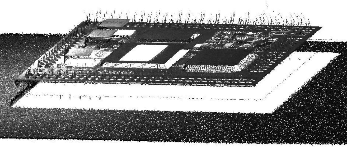 |
Cluster denoising (distance threshold 0.258 mm, effective points 100)) | 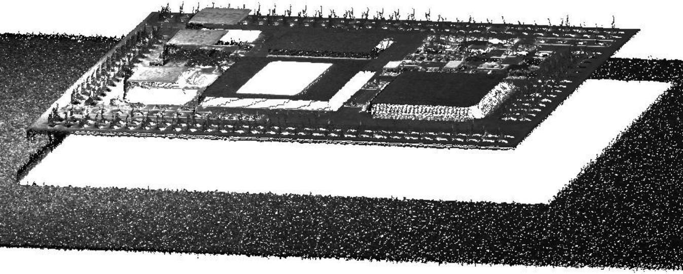 |
Edge denoising
Edge denoising function is only available in binocular mode. Its principle is to remove unreliable point clouds within the surrounding area of invalid points, thereby reducing noise in the point cloud. The larger the edge denoising value, the stronger the denoising effect, but it may cause loss of detailed information in the point cloud.
| operation | Example |
|---|---|
| No edge denoising | 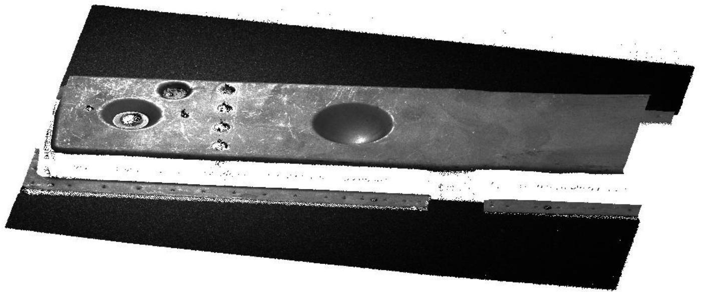 |
| Edge denoising level is 1 | 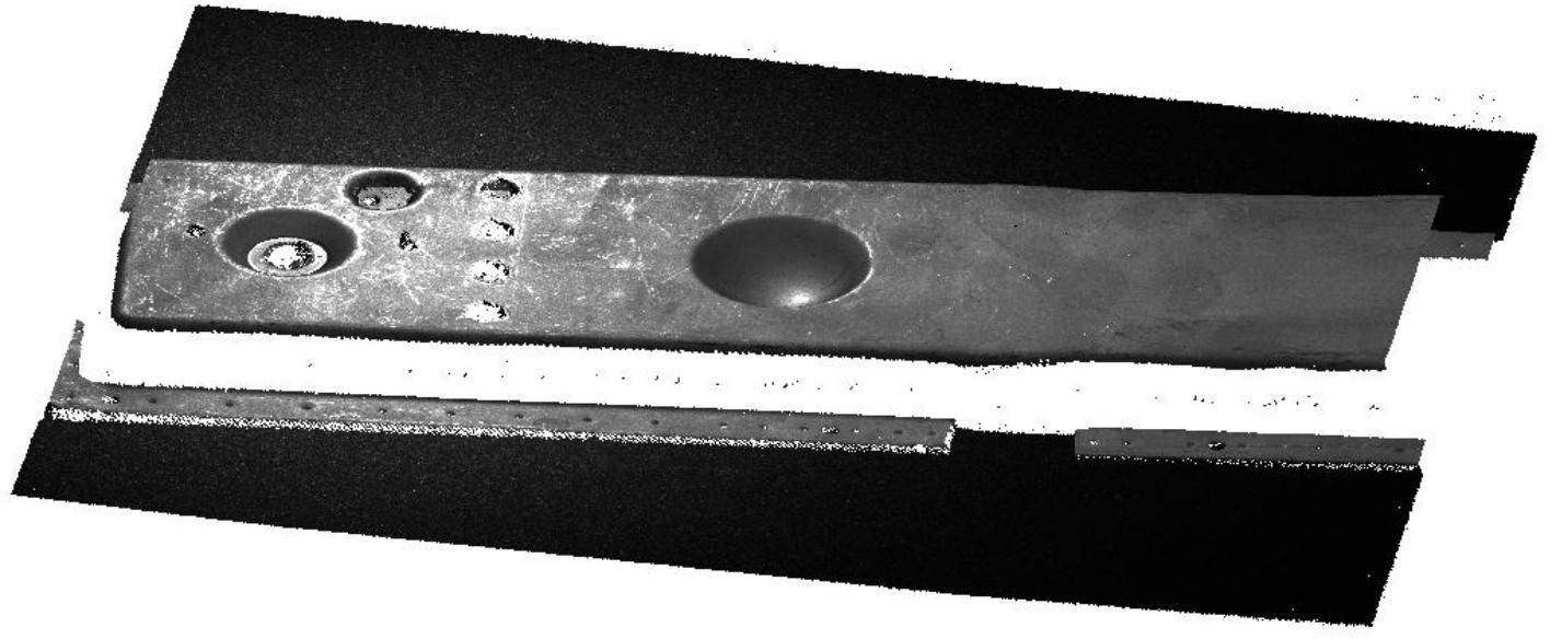 |
| Edge denoising level is 3 | 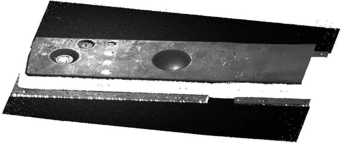 |
Smoothing level
The smoothing level is used to adjust the smoothness of the point cloud and is divided into four levels: Off, Weak, Medium, and Strong, with the default being Off. The changes in point cloud smoothing can be observed by viewing the thickness of the point cloud.
| operation | Example |
|---|---|
| Smoothing off | 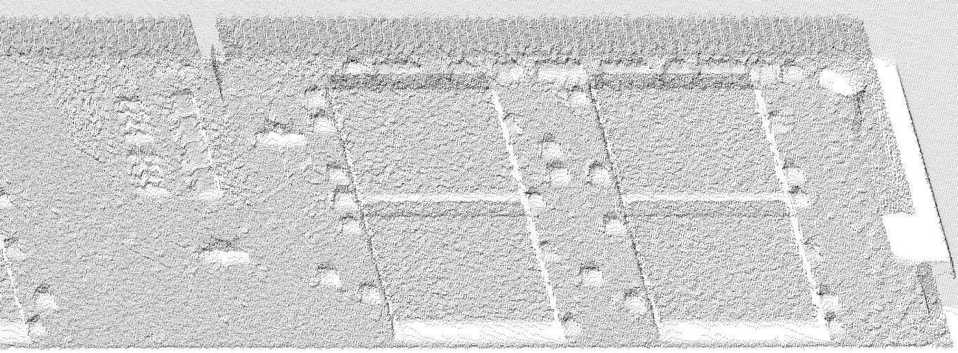 |
| Smoothing level is strong | 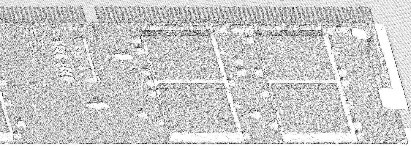 |
Downsampling distance
Downsampling is applied to the generated point cloud. When the downsampling spacing is smaller than the original point cloud spacing, the point cloud remains basically unchanged. When the downsampling spacing is larger than the original point cloud spacing, the point cloud spacing is approximately equal to the average downsampling spacing. The larger the downsampling spacing, the fewer the number of points.
| Downsampling spacing – 1 mm | Downsampling spacing 1 mm |
|---|---|
 |  |
Calculate normal vectors
By checking “Yes” and setting the normal calculation radius, the normal vector of the point cloud can be calculated.
The normal vector of the point cloud can be roughly regarded as a collection of perpendicular lines on the surface of the photographed object. The normal vector calculation radius affects the accuracy of the normal vector. If it is set too small, there will not be enough points to calculate the local model, and the result may be biased; if it is set too small, the normal vector calculation radius will affect the accuracy of the normal vector.
If it is too large, the calculation process may take longer and the result will be smooth.
Calculate and display normal vectors
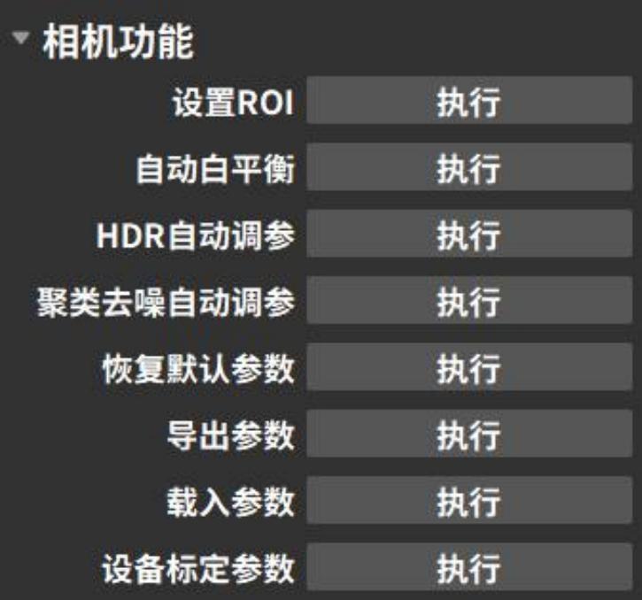
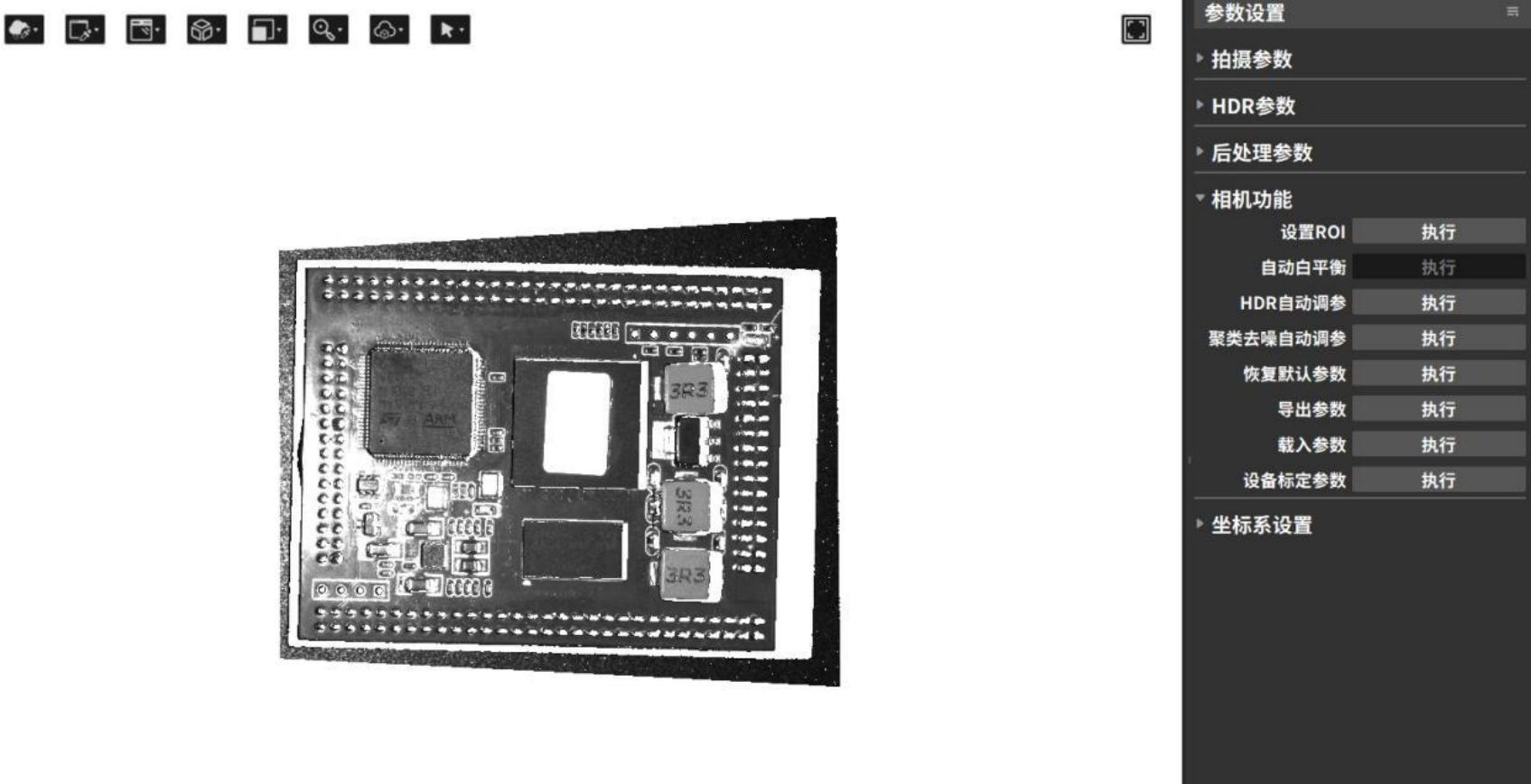
3.4.5 Camera Features
Camera function options can automatically set parameters according to shooting requirements. For already configured parameters, import and export operations can be performed, allowing direct use in subsequent shoots. The configurable parameter options depend on the type of connected camera. The following image shows the shooting parameters for a monocular color camera as an example.
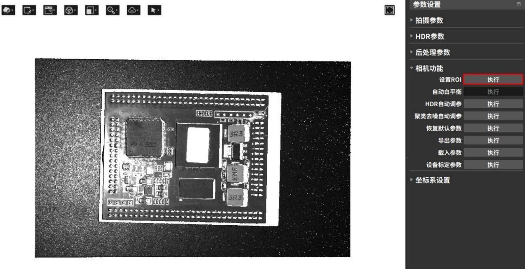
Set ROI (Region of Interest)
The Set ROI function is only applicable in monocular mode. When acquiring the point cloud of the measured object, the original field of view can be cropped to obtain a custom field of view. The parts not retained will no longer contain data. The selected field of view area is called the ROI (Region of Interest). Setting the ROI can reduce the amount of data and decrease data processing time, thereby improving detection efficiency. The operation steps are as follows:
- Click the button to execute the Set ROI.
- Select the ROI area through the pop-up window.
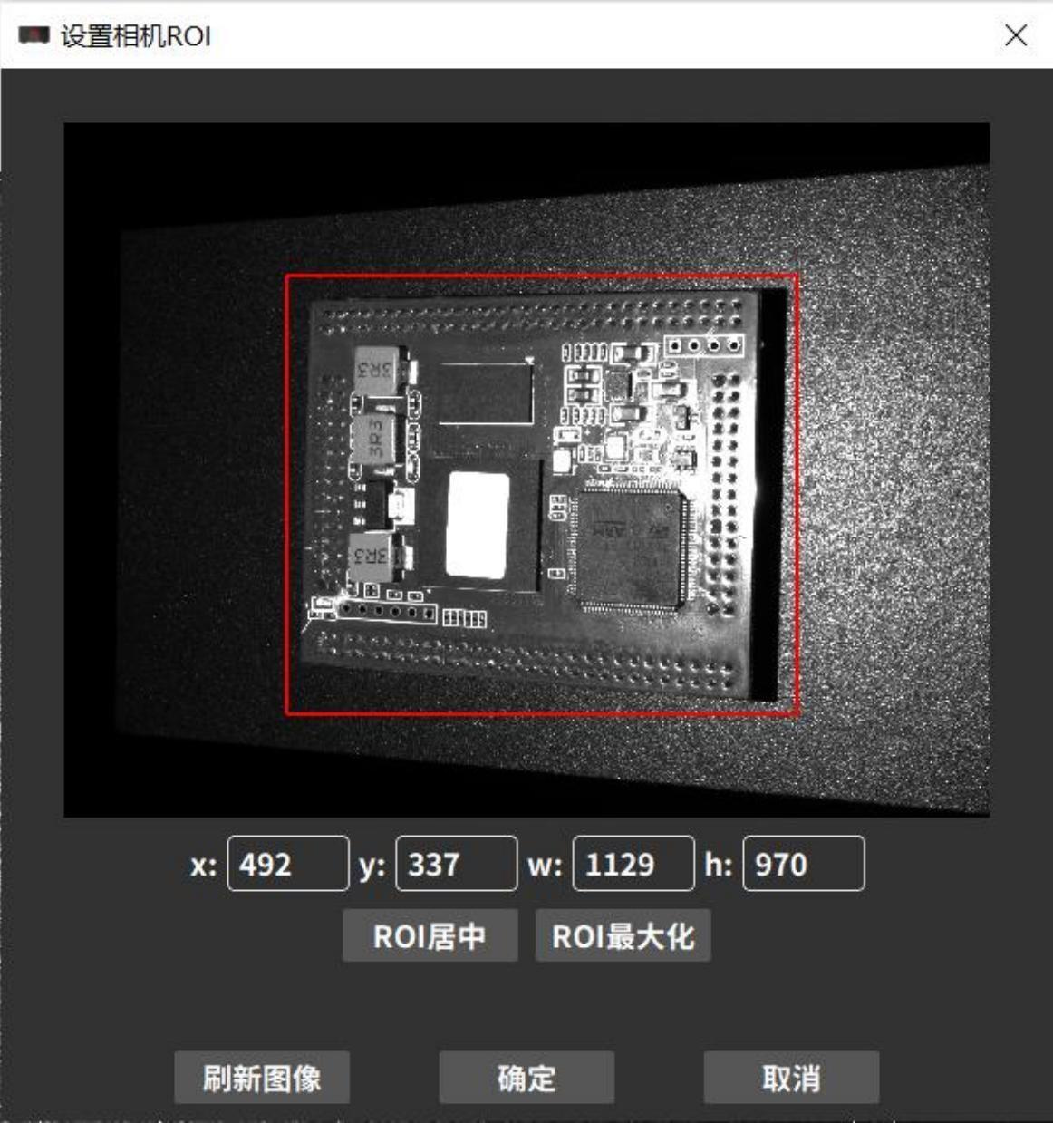
- After the setting takes effect, perform the shooting again to obtain the point cloud, 2D image, depth map, and confidence map of the cropped area.
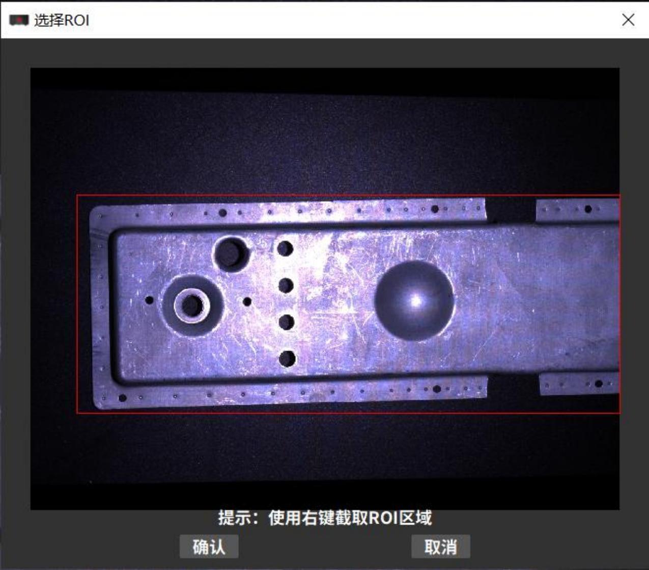
Automatic white balance
The automatic white balance function determines the basic color temperature of the photo and achieves color balance by comparing the selected area of interest with 18% neutral gray.
This function is only available for color cameras. Use the automatic white balance function when the 2D images taken with a color camera have distorted colors.。
- Click the button to perform automatic white balance.
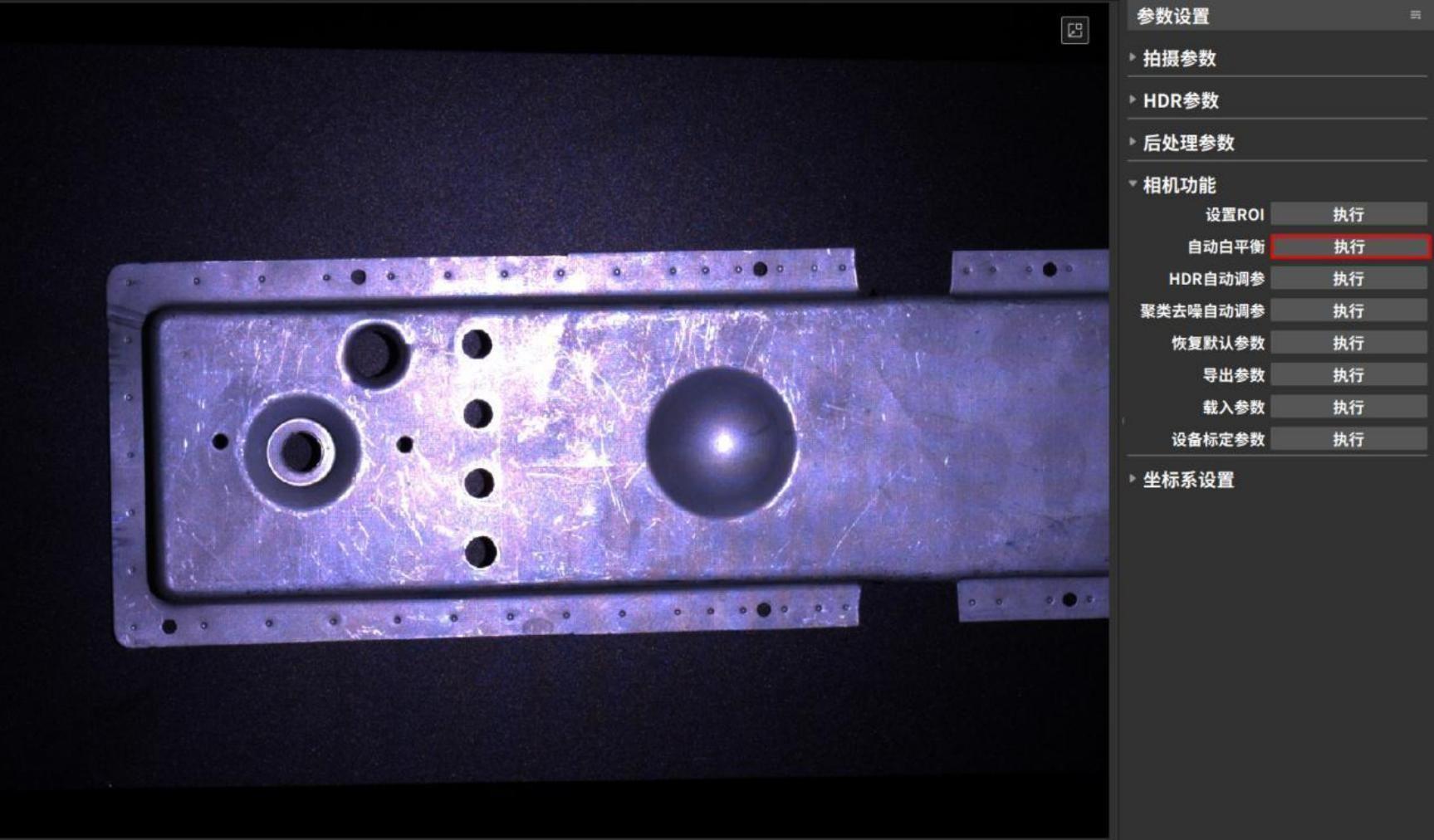
- Select ROI (Region of Interest) via the pop-up window.
You can get a 2D image after automatic white balance.。
HDR automatic parameter adjustment
The HDR automatic parameter adjustment function can automatically set HDR parameters according to the ROI area selected by the user.
Perform HDR automatic parameter adjustment and write the generated shooting parameters to the camera for use in the next shooting.
The HDR parameters that can be automatically set by this function include: additional exposure times, exposure time for each 3D exposure, gain, number of scans, and projection brightness. The operation steps are as follows:
- Click the [Execute] button to execute HDR automatic parameter adjustment.
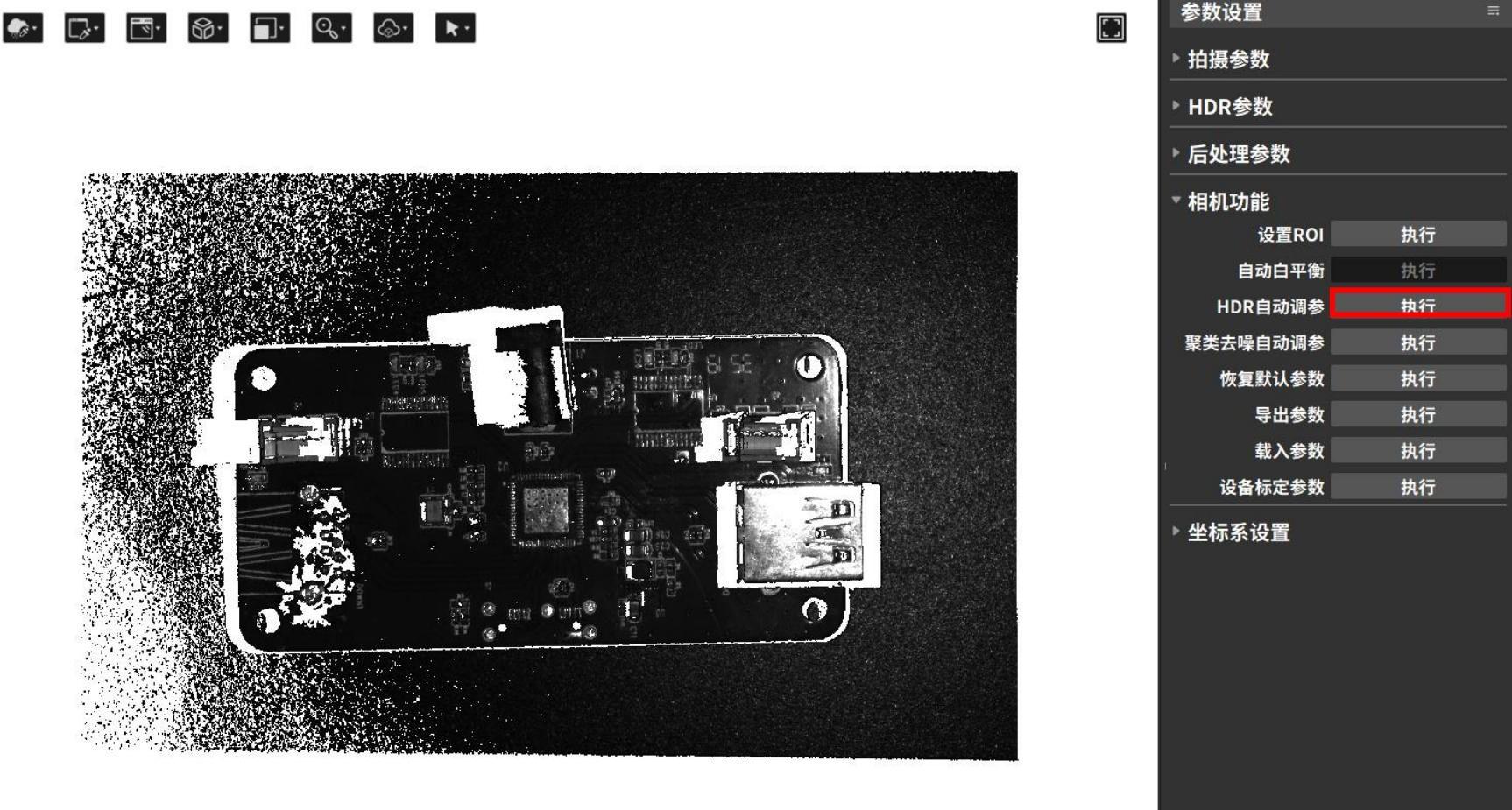
- Select ROI (region of interest) in the pop-up window and click [Confirm].
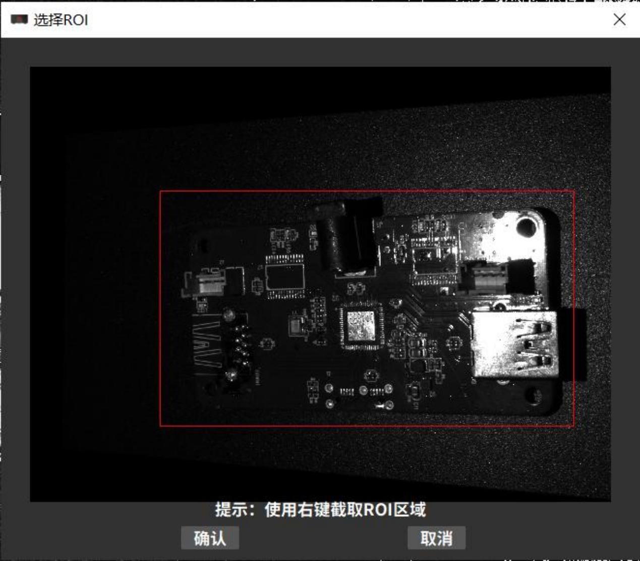
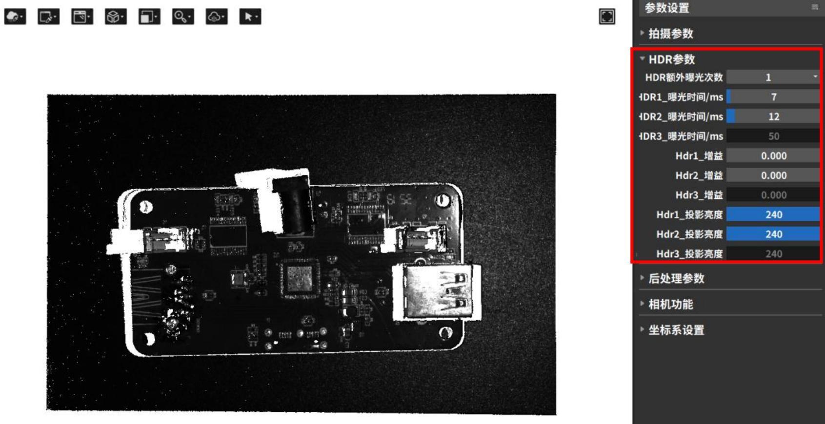
- The software automatically adjusts parameters and captures the 3D point cloud. You can view the relevant parameter updates in the HDR parameter column.
Automatic parameter tuning for clustering denoising
The clustering denoising function can remove abnormal isolated and clustered point cloud noise points and also includes an auto-parameter adjustment option. By clicking the [Execute] button, the system can automatically adjust the distance threshold and minimum number of valid points, and write the adjusted parameters into the camera.
| Abnormal flying point cloud noise points | Clustering denoising auto-parameter adjustment (Distance threshold: 0.237 mm, Minimum valid points: 40) |
|---|---|
 |  |
Export Parameters
In actual shooting scenarios, it is sometimes necessary to set a fixed set of parameters for a project. After adjusting the parameters, the Save Parameters function can be used to export the camera parameters as a .json configuration file
Loading parameters
When it is necessary to use a previously saved parameter set, the Load Parameters function can be used to load the configuration file parameters into the shooting interface.
![]()
Common parameter loading exceptions are as follows:
- Incorrect configuration file format. Currently, only .json format is supported for import.
- Camera mode mismatch. Binocular camera modes include left camera, right camera, and dual camera, while monocular cameras do not support camera mode selection. The configuration parameters of these two types of cameras are not interchangeable.。
- Unsupported shooting mode. Regular cameras have Standard/Fast modes, while laser cameras have Anti-Interference/High-Precision modes. The configuration parameters of these two types of cameras are not interchangeable.
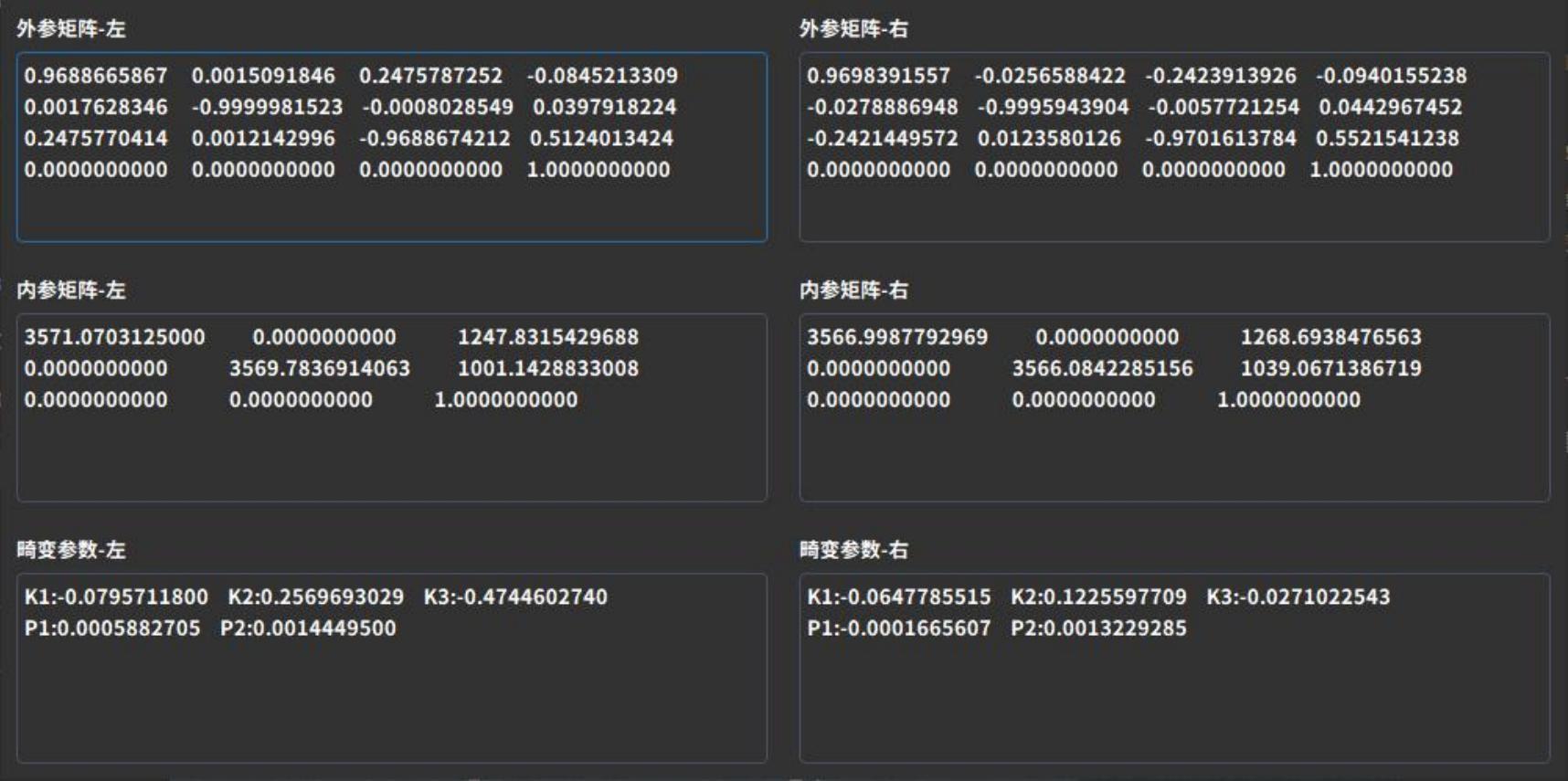
Equipment calibration parameters
Displays camera calibration parameters, including the extrinsic matrix, intrinsic matrix, and distortion coefficients. If the camera calibration parameters differ from those at the factory, the shooting results will be affected.
Camera extrinsics: Parameters in the world coordinate system, such as the camera’s position and rotation direction. They consist of a rotation matrix and a translation matrix, which together describe how to transform points from the world coordinate system to the camera coordinate system.
Camera intrinsics: Parameters related to the camera’s own characteristics, such as focal length and pixel size.
Distortion parameters: Refer to image distortion phenomena caused during shooting by optical system deformation, concave reflections, and other factors, affecting image processing. These are numerical parameters used to describe image distortion, commonly represented by radial distortion Rd and tangential distortion coefficient K1.
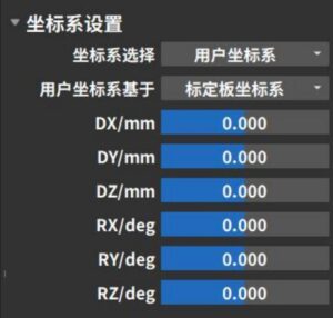
3.4.6 Coordinate system settings
Coordinate system settings include calibration board coordinate system, user coordinate system, and left/right camera coordinate system settings.
When it is necessary to change the position and orientation of the point cloud relative to the coordinate axes, the “Coordinate System Settings” function can be used to modify the reference coordinate system of the data. After modification, the shape of the point cloud and the relative positions of internal points will not change.
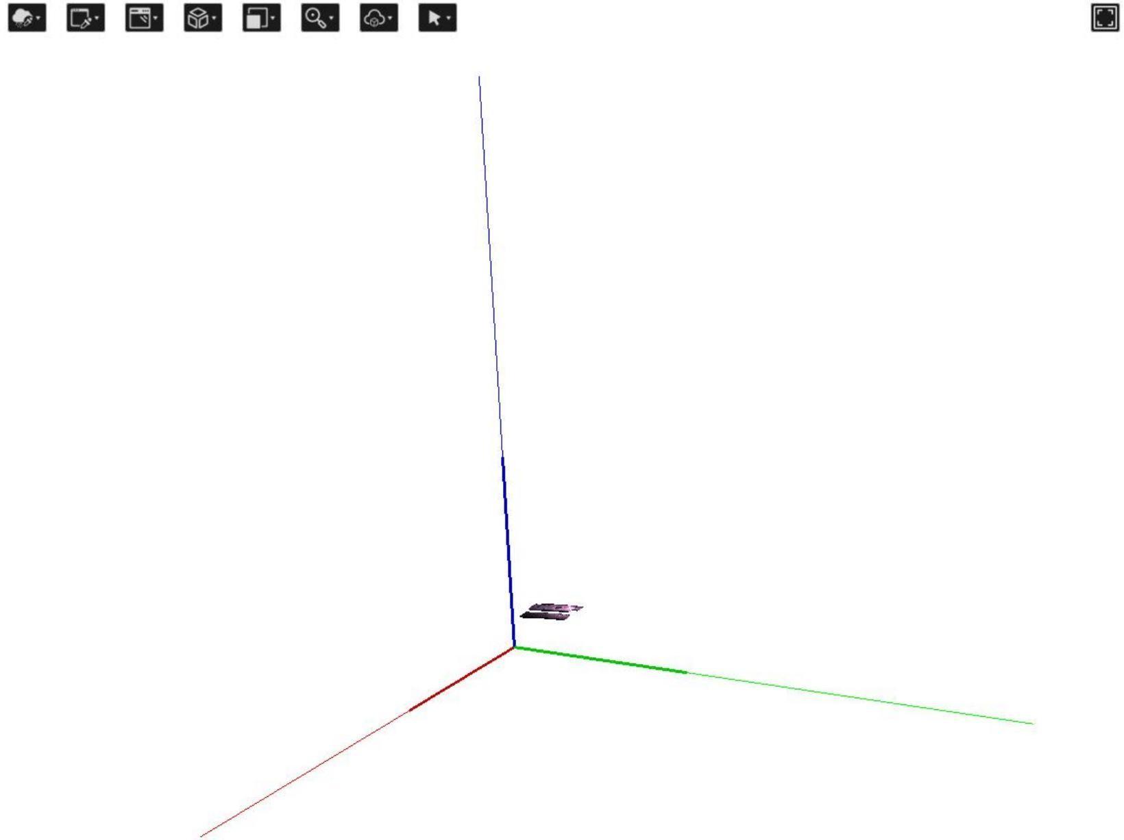
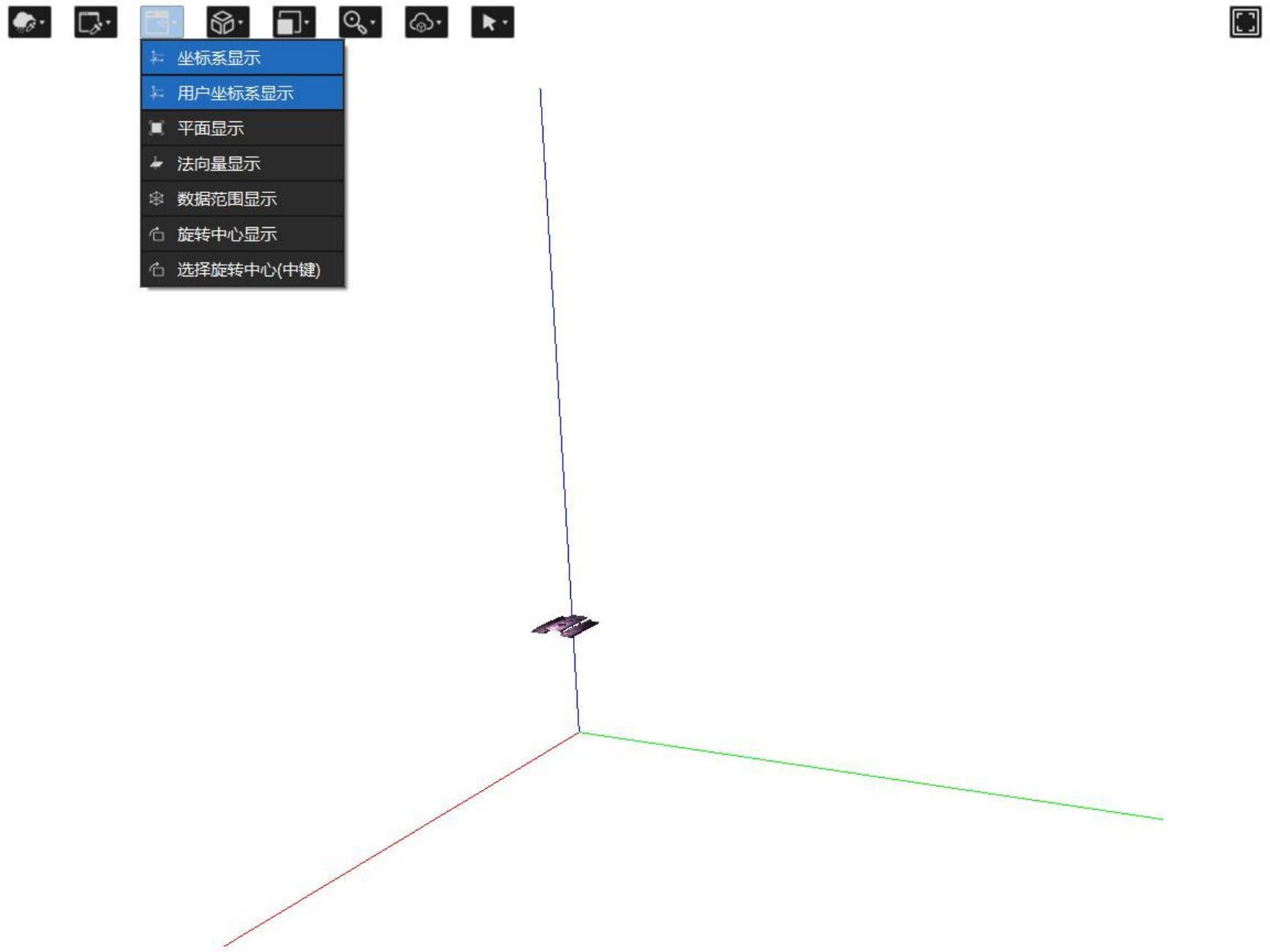
Before use, ensure that the “User Coordinate System Display” option in the point cloud display area is enabled. You can also enable the “Coordinate System Display” option to check whether the transformation magnitude of the user coordinate system relative to the original coordinate system meets the requirements.
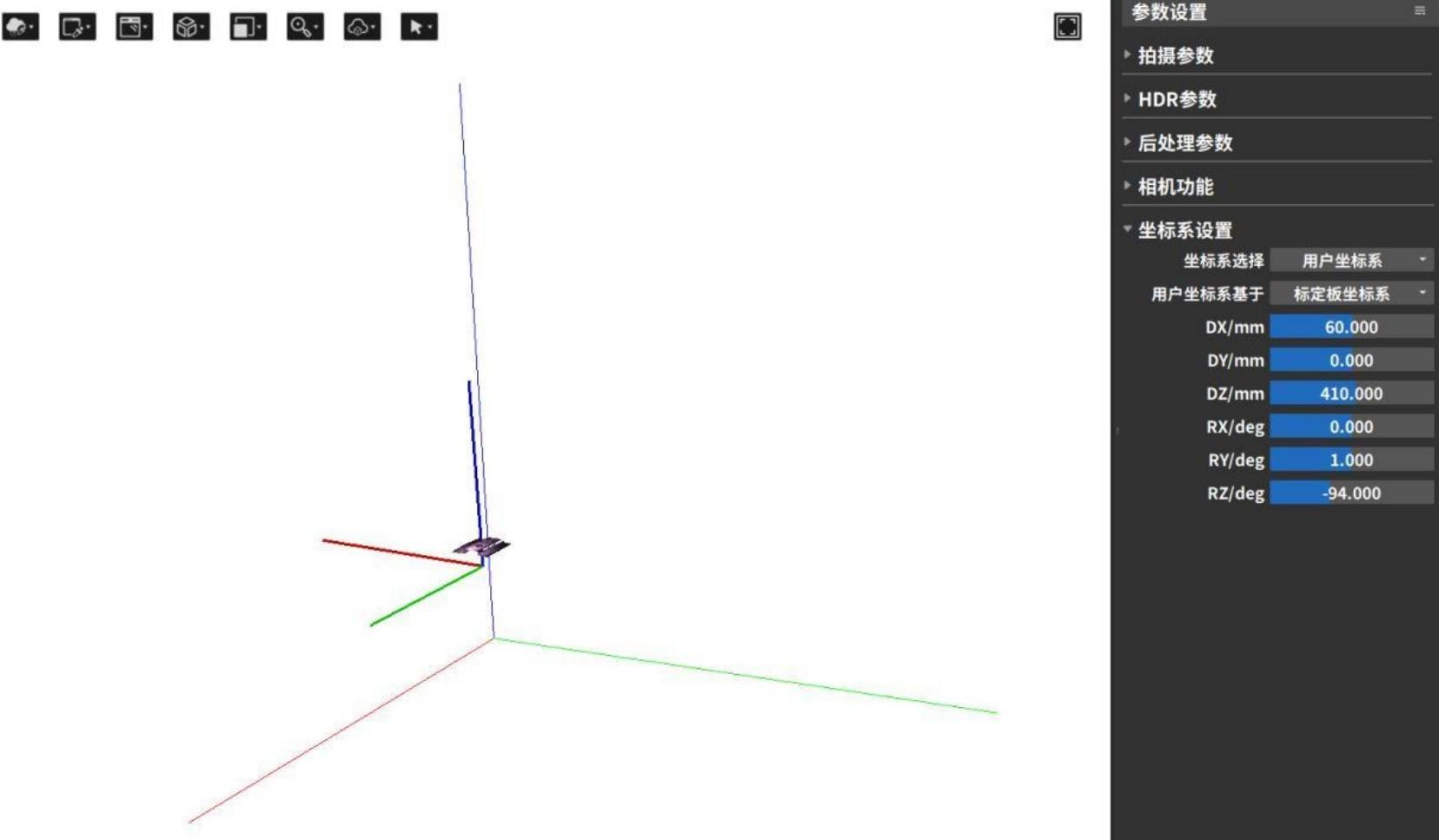
- In “Coordinate System Selection,” choose the target coordinate system type to transform to (Camera Coordinate System / Calibration Board Coordinate System / User Coordinate System; for binocular cameras, Left Camera Coordinate System / Right Camera Coordinate System can also be selected). In “User Coordinate System Based On,” select the original coordinate system before the transformation.
- Enter the coordinate system’s X, Y, Z offset values (DX, DY, DZ) and rotation values (RX, RY, RZ). You can also directly drag the user coordinate system axes in the point cloud display area with the mouse. For easier visualization, the modified coordinate system axes are displayed thicker and shorter than the original axes.
After the modification is completed, the system will automatically calculate the transformed coordinate system based on the transformation matrix, and the point cloud display area will automatically update the position and orientation of the point cloud.。