
Shipyard teams lose time when varied parts need repeated teaching. The robot waits. Welders wait. Rework can quietly grow.
Intelligent welding helps shipyard small sub-assemblies by using 3D scanning, seam recognition, automatic positioning, and automatic path generation. I see the real value in less manual programming, more stable weld quality, and better fit for high-mix, low-volume parts.
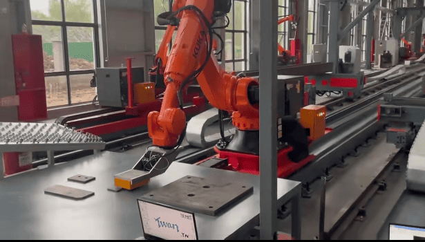
I have worked around domestic top-tier shipbuilding manufacturing scenarios, and I learned one clear lesson. The hardest question was not, “Can the robot weld fast?” The real question was, “Can the system understand the real part in front of it?” Small sub-assemblies and medium-resistance components often look simple on paper. They become complex in the workshop. The gap changes. The seam shifts. The fixture has tolerance. The operator needs a system that can deal with real production, not only a perfect demo part.
Why Is Shipbuilding Small Sub-Assembly Welding Hard to Automate?
A shipyard can buy a robot and still face slow production. Each part changes. Each change can create another teaching job.
Small sub-assembly welding is hard to automate because shipyards often handle many part types in small batches. I need the welding system to find the real seam position, handle assembly deviation, and create paths with less manual teaching.
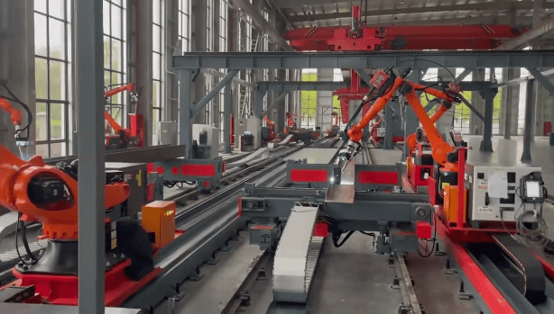
The Real Problem Is Part Variety
I see shipbuilding as a strong example of high-mix, low-volume production. One week can include many small structures, brackets, stiffeners, ribs, plates, and welded parts with different access conditions. The drawing may be clear, but the actual part can still have small differences after cutting, bending, fitting, and tack welding.
Traditional robot welding can work very well when the same part repeats many times. I do not reject that method. It has a strong place in stable batch production. The problem starts when every new part needs manual teaching. The programmer may spend more time preparing the path than the robot spends welding.
| Production factor | What I often see in shipyards | Why it matters for automation |
|---|---|---|
| Part variety | Many shapes and small batches | Manual teaching becomes slow |
| Assembly deviation | Real seam moves from the drawing | Fixed paths may miss the seam |
| Fixture condition | Some fixtures are simple or flexible | Part location may change |
| Weld access | Some seams are blocked or narrow | Robot posture must be checked |
| Batch size | Many jobs are not large batches | Programming time must be reduced |
I usually tell customers that automation must match the production rhythm. If the robot needs too much offline programming or hand teaching, the workshop may not get the expected return. The better direction is to let the system scan the real part, recognize welds, and generate usable paths. This does not remove process engineers. It helps them spend less time on repeated teaching and more time on welding process control.
What Makes Intelligent Welding Different from a Standard Robot Cell?
Many factories think the robot is the solution. I think the robot is only one part. The workflow decides the result.
Intelligent welding is different because it adds sensing and decision steps before welding. I use 3D vision scanning, seam recognition, automatic positioning, automatic path generation, and controlled welding execution to reduce repeated manual programming.
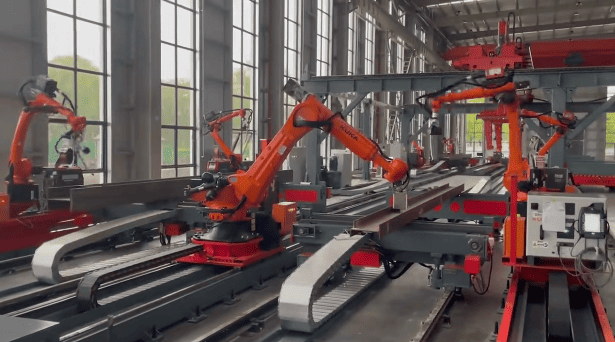
The Workflow Is the Core Value
When I discuss intelligent welding with shipyard teams, I focus on the full workflow. A welding robot without good part recognition can only follow the path that people give it. If the part position changes, the path must change. If the weld type changes, the program must change. This creates pressure on programmers and operators.
A more useful system starts with 3D vision. The scanner captures the real geometry. The software then identifies possible weld seams. The system locates start points, end points, seam direction, and joint position. Then it creates a robot path. The welding process still needs correct settings. The torch angle, travel speed, wire feed, laser power, or arc parameters must match the material, thickness, and weld requirement.
| Step | What the system does | What I check in real projects |
|---|---|---|
| 3D scanning | Captures the actual part shape | Scan range, blind areas, surface condition |
| Seam recognition | Finds the weld seam | Joint type, gap, tack weld influence |
| Positioning | Locates real seam coordinates | Accuracy and repeatability |
| Path generation | Builds robot motion | Torch angle and collision risk |
| Welding execution | Completes the weld | Penetration, appearance, spatter, stability |
I do not describe this as magic. I see it as a practical chain of steps. If one step is weak, the whole result becomes unstable. Good scanning cannot fix a wrong welding process. Good welding power cannot fix a missing seam position. The value comes when the system connects recognition, path planning, and welding execution in one usable production flow.
Why Is Faster Welding Not Enough for Shipyard Production Managers?
Fast welding can look attractive in a test. The problem appears later when rework, poor penetration, and unstable appearance cost more time.
Faster welding is not enough because shipyard teams also need stable quality, reliable penetration, consistent seam shape, and lower rework risk. I judge success by the full production result, not only travel speed.
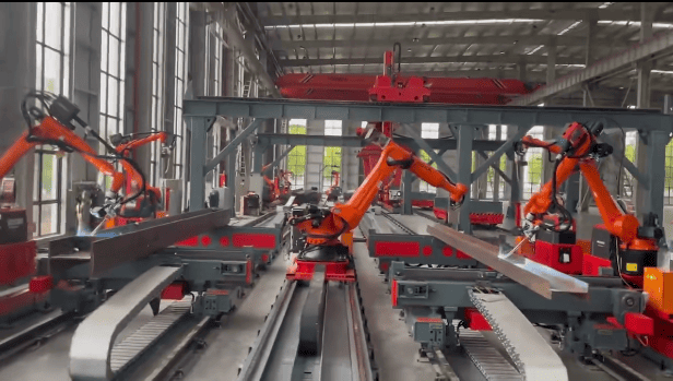
Quality Decides the Real Output
I have seen customers focus first on welding speed. I understand that view because shipyards face labor pressure and delivery pressure. A faster weld can help. Yet I also know that a fast unstable weld can create more work. If the seam needs grinding, repair, or inspection rejection, the speed number loses meaning.
For small sub-assemblies and medium-resistance components, the goal should be stable qualified output. The weld should meet the required penetration and appearance. The system should keep the seam in the correct place. The heat input should match the material and thickness. The robot posture should allow the torch or laser head to reach the weld without collision.
| Output goal | Why I care about it | What can affect it |
|---|---|---|
| Penetration | The weld must meet strength needs | Power, speed, joint fit-up, gap |
| Seam appearance | The part should need less finishing | Torch angle, path stability, process settings |
| Repeatability | The next part should be similar | Fixture stability and scan accuracy |
| Low rework | The workshop saves real time | Recognition quality and process control |
| Operator confidence | The team must trust the system | Easy operation and clear feedback |
I usually recommend a trial based on real parts, not only a standard sample plate. The trial should include normal part deviation, real tack welds, real fixtures, and real weld requirements. This gives the production manager a better view. It also helps my team adjust the scanning logic, path rules, and welding parameters before large-scale use.
Where Does Intelligent Welding Fit Best in Small Sub-Assemblies and Medium-Resistance Components?
Some teams expect one system to weld everything. That creates risk. I prefer to define suitable parts first.
Intelligent welding fits best where weld seams are visible or scannable, access is possible, material and thickness are suitable, and part variety makes manual programming costly. I do not treat it as a universal solution.
Suitability Comes Before Purchase
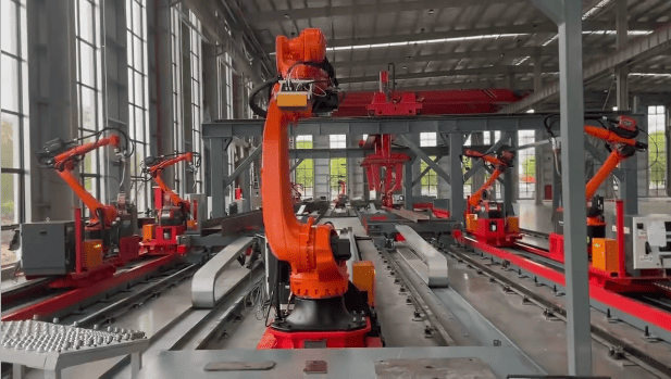
In shipbuilding, not every component should be the first target for intelligent welding. I like to start with parts that have clear value and controllable risk. Small sub-assemblies are often good candidates because they repeat by type but still change in size or shape. Medium-resistance components can also be suitable when the robot can reach the weld, and the scanner can see enough geometry.
I use “medium-resistance components” to describe parts that are not fully open and easy, but also not so blocked that automation becomes unreasonable. These parts may have ribs, plates, corners, or structural details that create some access limits. The system must consider torch posture, collision space, and seam visibility.
| Suitability factor | Better condition | Risk condition |
|---|---|---|
| Seam visibility | Scanner can see the joint clearly | Joint is hidden or blocked |
| Access space | Robot can keep a good welding angle | Torch collides with nearby structure |
| Part stability | Fixture holds the part firmly | Part moves during welding |
| Material and thickness | Process window is known | Thickness changes without control |
| Groove design | Joint is consistent enough | Gap or groove changes too much |
| Weld requirement | Requirement matches the process | Requirement needs special approval |
I do not promise that intelligent welding can cover all shipbuilding parts. I also do not say manual welding has no value. Skilled welders remain important, especially for difficult access, special repair, and process judgment. The stronger use case is different. I use intelligent welding to reduce repeated programming work and improve consistency on suitable non-standard parts. That is where the return is easier to defend.
How Should a Shipyard Evaluate an Intelligent Welding Project Before Buying?
A wrong evaluation can turn a good machine into a poor investment. The factory may choose based on a demo that does not match production.
A shipyard should evaluate drawings, materials, thickness, weld types, accessibility, fixtures, batch patterns, quality standards, and support needs. I prefer to test real parts before I confirm the solution design.
I Start with the Part, Not the Machine
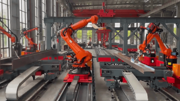
When I speak with a shipyard production manager or welding engineer, I ask for practical information first. I do not start by pushing a robot model. I need drawings, photos, videos, material grades, thickness ranges, joint types, groove details, weld length, welding position, and expected quality. I also ask about current cycle time, rework points, and programming workload.
The best evaluation includes both technical and production questions. The system must weld the part. It must also fit the workshop flow. The operator must load and unload parts safely. The scanner must have a stable position. The robot must have enough reach. The software must be easy enough for the team to use every day.
| Evaluation item | What I ask for | Why it matters |
|---|---|---|
| Drawings and 3D files | Part shape and weld location | I need to judge path and access |
| Material and thickness | Steel type and thickness range | I need to select process settings |
| Weld type | Fillet, butt, lap, groove, or mixed | I need to build recognition rules |
| Fixture method | How the part is held | I need to judge repeatability |
| Batch pattern | Quantity and variation | I need to judge programming value |
| Quality requirement | Penetration and inspection needs | I need to avoid wrong promises |
| Site support | Training and service needs | I need to plan delivery correctly |
I also set clear boundaries. Intelligent welding still needs welding procedure knowledge. It still needs process confirmation by the customer side. It still needs operators who understand loading, safety, and basic maintenance. My role is to provide the system, integration, training, and support. The customer role is to confirm production standards and use the system in a controlled way.
Conclusion
I see intelligent welding as a practical way to reduce teaching work and improve consistency when shipyard parts are suitable for scanning, access, and stable welding.


