
Collaborative Robot
Practical, value-focused automation for everyday production. Choose from seven six-axis models and configure a system for welding, palletizing, cutting, handling or other repeatable industrial tasks. A versatile option for businesses balancing capability, flexibility and investment.
FR3MT · FR3 · FR5 · FR10 · FR16 · FR20 · FR30

Teach pendant controls, explained.
This 21-second hardware overview identifies the program start and stop buttons, cable connection, emergency stop, three-position enabling switch and manual jogging controls.
English-captioned hardware overview (silent). This clip shows the teach pendant, not a welding cycle. Pendant layout may vary with the supplied version.
Smart Tool makes path teaching more direct.
The optional Smart Tool handle places configurable controls at the robot wrist. Operators can record motion points, build straight and circular paths, and insert I/O commands through the web-based teaching workflow.
It supports standalone use or integration with a compatible force sensor. The hardware and communication settings must match the selected configuration.
- PTP: point-to-point moves between taught positions.
- LIN: linear tool motion for straight path segments.
- ARC: circular segments defined through taught points.
- I/O: configured output commands, including arc-start and arc-stop integration.
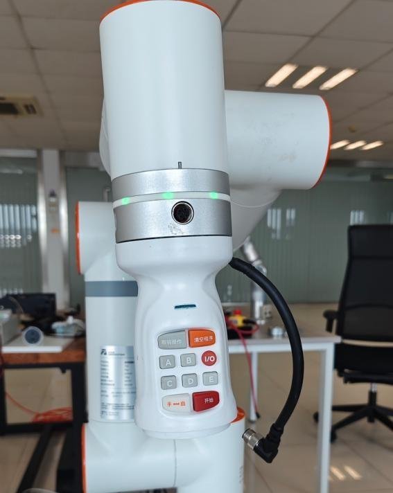
Mounted at the robot wrist
The handle mounts through the TCP connector. Confirm tool clearance, flange compatibility and the combined tool load before integration.
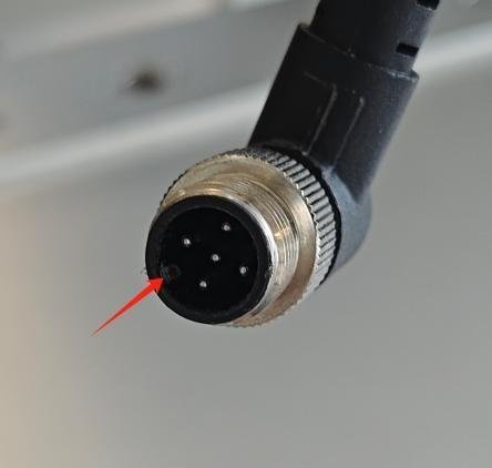
RS-485 connection
The tutorial uses an RS-485 connection at the robot end. Device configuration is completed in the web teaching interface.
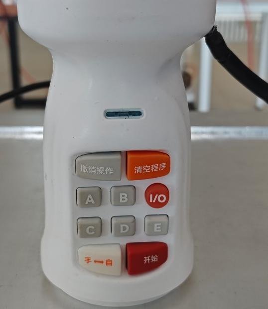
Five configurable buttons
A/B/C/D/E can be assigned functions such as PTP, LIN, ARC, New Program and Save Program. Dedicated controls include Undo, Clear Program, Manual/Auto, Start and I/O.
Button assignments and available functions depend on the installed Smart Tool and software version.
Configure
Select the end device and assign the handle buttons in the teaching interface.
Teach
Guide the arm to the required positions and record the path points.
Build the process
Add linear or circular motion and the required welding I/O commands.
Validate & run
Check the program, tool setup and process parameters before production.
A robot arm is the start of a welding system.
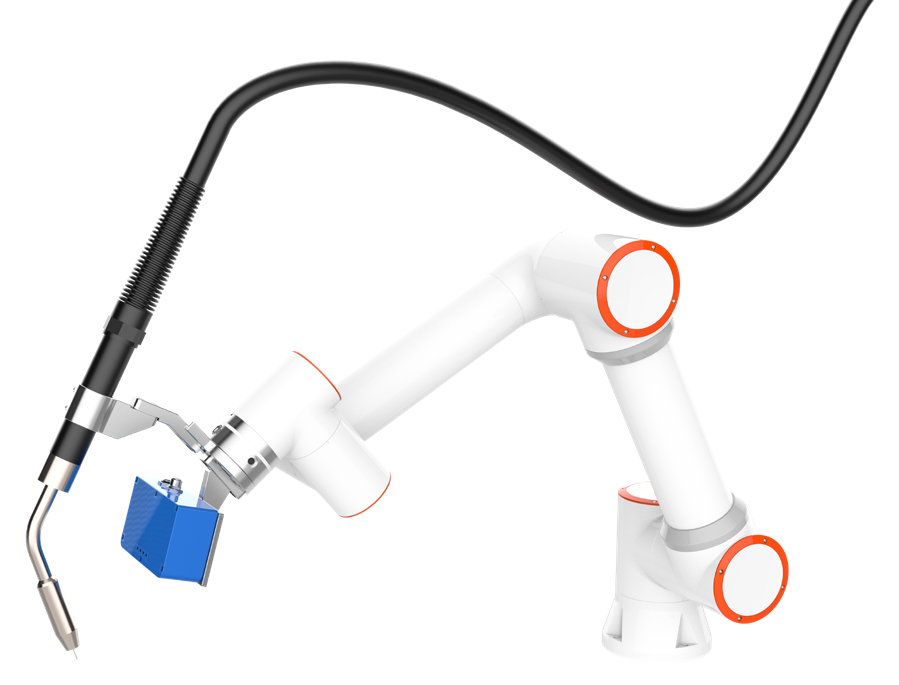
A working cell combines the arm with a welding power source, wire feeder, torch, workholding and coordinated controls. Smart Tool teaching, a mobile platform and vision can be added to suit the job.

Welding process capabilities
The supplied brochures describe spot and stitch welding, straight and circular seams, weaving, and multilayer/multipass welding. Wire touch sensing and seam tracking are available within compatible configured systems.
Specify the full equipment package
- Arm model, mounting arrangement and working envelope.
- Power source, feeder, torch, cable routing and cooling.
- Smart Tool, fixtures, table or mobile base.
- Process software, sensing and I/O integration.
Optional seam finding & tracking
A compatible laser tracking system can locate the joint and provide position corrections while welding. The supplied integration manual describes single-point and multipoint locating, intersection calculations and real-time tracking examples.
Reliable results depend on sensor mounting, TCP and sensor calibration, communication setup, joint geometry and the validated welding program. Seam tracking is a configured system option, not an inherent function of the bare arm.
Seven models. A clear specification comparison.
Compare payload and reach together. The heaviest payload model is not the longest-reaching: FR20 reaches 1854 mm, while FR30 offers a 30 kg payload at 1403 mm.
| Model | Payload | Reach (mm) | Repeatability (mm) | TCP speed (m/s) | Arm mass (kg) | Base Ø (mm) | Avg. / peak power (W) |
|---|---|---|---|---|---|---|---|
| FR3MT | 3 kg* | 622 | ±0.05 | 1 | ≈10 | 125 | 200 / 230 |
| FR3 | 3 kg | 622 | ±0.02 | 1 | ≈15 | 128 | 220 / 280 |
| FR5 | 5 kg | 922 | ±0.02 | 1 | ≈22 | 149 | 260 / 310 |
| FR10 | 10 kg | 1400 | ±0.05 | 1.5 | ≈40 | 190 | 300 / 500 |
| FR16 | 16 kg | 1034 | ±0.03 | 1 | ≈40 | 190 | 310 / 410 |
| FR20 | 20 kg | 1854 | ±0.1 | 2 | ≈85 | 240 | 620 / 810 |
| FR30 | 30 kg | 1403 | ±0.1 | 2 | ≈85 | 240 | 600 / 910 |
Specifications transcribed from the supplied FR-series V8.0 brochure dated 2024-09-20. TCP speed and electrical power are typical values; power is reported under the brochure's test conditions. Repeatability is not absolute positioning accuracy.
* FR3MT is rated at 3 kg; the brochure separately lists 5 kg instantaneous capacity. Do not treat the instantaneous value as a continuous payload rating. Tooling, accessories and the workpiece must all be included when assessing the load.
How to select the right model
- Calculate the complete tool load. Include the torch or gripper, adapter, sensor, carried workpiece and relevant cable forces. Check center of gravity and inertia as well as mass.
- Check the full working envelope. Verify every required tool orientation, fixture clearance and approach/retract path, rather than using reach alone.
- Match motion to the process. Validate the required cycle time, welding speed or handling trajectory with the selected payload.
- Confirm the application package. Choose the controls, protection level, peripheral interfaces and installation arrangement before ordering.
Integrate the robot into your production.
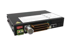
Robot controller
The brochure lists AC and DC controller variants. Match controller capacity and supply to the selected arm; FR20/FR30 use the higher-output controller family.
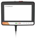
Teach pendant & Web App
An optional 10.1-inch pendant provides a dedicated interface. The Web App can also be accessed from a compatible computer, tablet or phone.
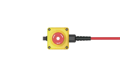
Safety button box
The operator button box provides basic interaction such as mode switching, drag teaching, point recording, start/stop and shutdown, as described in the brochure.
Controller interfaces
- 16 digital inputs and 16 digital outputs.
- 2 analog inputs, 2 analog outputs and 2 high-speed pulse inputs.
- TCP/IP, I/O and Modbus TCP/RTU standard communication.
- Optional CC-Link, PROFINET, EtherNet/IP and EtherCAT interfaces.
- SDK support listed for C#, C++, Python, ROS and ROS 2.
External axes & peripherals
The supplied configuration material shows controller + PLC communication over UDP and controller + servo-drive communication over RS-485 for external-axis setups.
Positioners, linear tracks, grippers, force sensors and vision devices require compatible hardware, software and commissioning. Confirm supported devices and coordinated-motion requirements for the intended system.
One robot family. Multiple application packages.
The end effector and process equipment determine what the system can do. These examples show ecosystem configurations rather than equipment included with every arm.
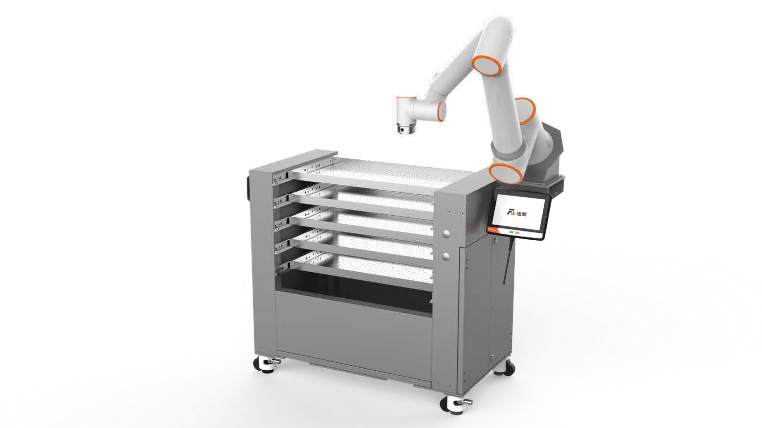
Machine tending
Configure gripping, part presentation and machine interfaces for loading and unloading. Confirm machine access, part weight and cycle requirements.
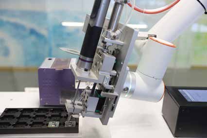
Assembly & screwdriving
Combine the arm with a tightening tool and part fixture. Torque control, fastener presentation and traceability depend on the selected equipment.
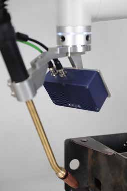
Dispensing & gluing
Pair the robot with a dispensing system to follow repeatable application paths. Material flow and process timing must be coordinated with the motion.
Palletizing
The ecosystem brochure includes fixed and lifting-column palletizing stations. Gripper type, carton dimensions, payload and stack height define the final configuration.
Vision-guided picking
Combine a compatible 3D camera, vision software and gripper for part detection and picking. Assess part geometry, surface finish and presentation conditions.
Handling & conveyor tasks
Coordinate the arm with fixtures, conveyors and sensors to transfer components between operations. Validate tracking, gripping and transfer timing together.
Cutting integration
Use a suitable cutting tool, process source and fixtures to build a cutting application. Confirm tool load, path access, cut quality requirements, extraction and process-specific protection during system design.
Spraying applications
Configure a suitable spray tool, fluid supply and process controls for coating tasks. Select the robot protection and installation arrangement for the coating material and operating environment.
Explosion-protected configurations
Dedicated explosion-protected robot and cabinet options are described in the supplied brochure. These require project-specific selection and verification for the intended hazardous area; a standard arm is not an explosion-protected system.
Define what is included before you order.
Confirm the robot package
- Selected robot model and controller.
- Button box, power and robot connection cables.
- Mounting hardware and installation arrangement.
- Required software version, manuals and configuration records.
Specify optional equipment
- Smart Tool and compatible force sensor.
- Teach pendant and optional communication interfaces.
- Welding source, torch, feeder, cooling and fixtures.
- Seam tracking, vision, grippers and external axes.
- Mobile base, positioner or application workstation.
Pictures illustrate possible configurations. The final bill of materials and scope of supply should be confirmed in the quotation.
Commissioning matters
Plan mounting, payload and TCP setup, cable management, peripheral communication, teaching and application trials. A collaborative arm does not make every process suitable for unguarded operation; the complete cell and its tooling determine the required protective measures, particularly for welding heat, arc radiation and fumes.
What customers need to know.
Who is this collaborative robot designed for?
This range is positioned for mainstream industrial automation: businesses seeking a practical balance of capability, flexible deployment and investment for repeatable production tasks. Select the arm and application package according to the job, rather than choosing by price alone.
Does Smart Tool eliminate all programming and setup?
Smart Tool simplifies point teaching and motion-command creation at the wrist. The robot still needs the correct tool and payload settings, a configured program, peripheral integration and process validation.
Is ±0.02 mm available on every model?
No. The supplied brochure specifies ±0.02 mm repeatability for FR3 and FR5. Other models range from ±0.03 to ±0.1 mm. Repeatability describes returning to a taught pose; it is not a guarantee of finished-part or weld accuracy.
Are laser seam tracking and vision included?
They are application options. A compatible sensor, interface, software and calibration are required. The arm alone does not provide a complete vision or tracking system.
Which information helps with a welding quotation?
Provide drawings or photographs, material and thickness, joint type, weld length, part dimensions and weight, required throughput, available floor space and existing welding equipment.
Tell us what you want to automate.
Send your part drawings, task description, tool or payload requirements and target cycle time. JTCLASER can discuss the robot selection and application configuration with you.